A counter mainly works by adding one to its value every time it gets a pulse from the clock signal.
When a counter counts up in response to the clock, we say it is in “count-up” mode.
If it counts down instead, we call that “count-down” mode. There are also special counters that can do both, and these are known as bidirectional counters.
Counters are a type of sequential logic device that starts working when they receive a timing pulse or clock signal.
They can be made to work as either synchronous or asynchronous circuits. Synchronous counters change all their data bits at the same time with the clock signal.
In contrast asynchronous counters change their data bits at different times, one after the other, without waiting for the clock to signal them all at once.
So counters are basically devices that count in a specific order based on an external clock signal. The number of steps a counter goes through before starting over is called the modulus. In simple terms, the modulus tells us how many states the counter counts through.
Modulus Counters
We call these modulus counters or MOD counters. They are defined by how many states they go through before resetting. For example, a 2-bit counter counts from 00 to 11 in binary which is 0 to 3 in decimal.
This counter has a modulus of 4 because it goes through four steps: 00, 01, 10, and 11 before going back to 00. It takes four clock pulses to complete this cycle.
With just two bits, the maximum number of states we can have is 2 raised to the power of n (2^n). So for n = 2 we get 4 states. But we can design counters to count higher by connecting multiple stages together.
Mod-N Counters
A “Mod-N” counter needs N flip-flops to count one data bit and can produce 2^n different output states. Remember N is always a whole number.
We can see that MOD counters have modulus values that are powers of 2 like 2, 4, 8, and so on. The number of flip-flops we use and how we connect them will determine the type and modulus of the counter.
D-type Flip-Flops
MOD counters use flip-flops. A single flip-flop can count either 0 or 1, giving us a maximum count of 2. There are different types of flip-flops we could use like S-R, J-K, or T-type.
But to keep it simple we’ll focus on D-type flip-flops. These are also known as Data Latches because they use one data input and an external clock signal.
For instance the D-type flip-flop like the TTL 74LS74 can be made from S-R or J-K based designs depending on whether we want it to change state on the positive or negative edge of the clock pulse.
Here we’ll assume we’re using a positive edge-triggered flip-flop. If you want to learn more about D-type flip-flops, check out this link!
Understanding D-type Flip-flop and Truth Table
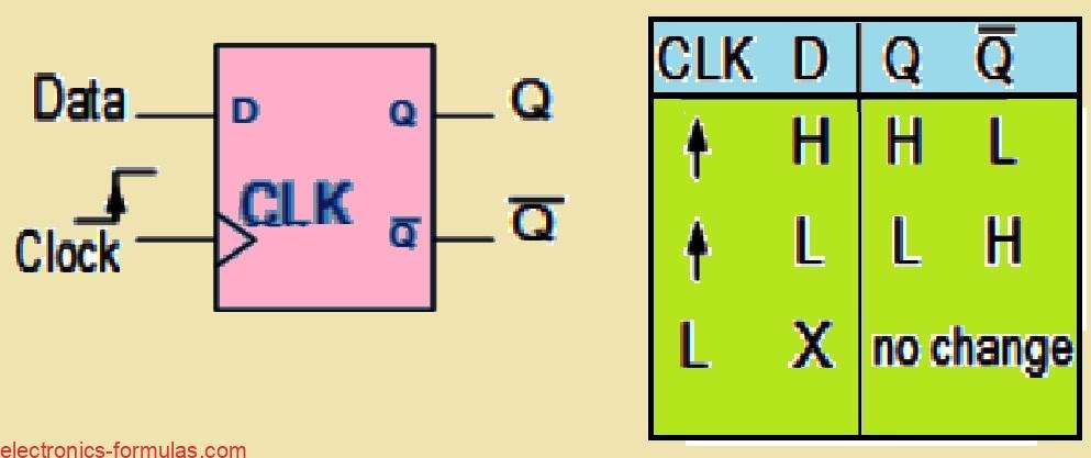
The D-type flip-flop (DFF) is pretty simple. It has one data input called “D” and a clock input labeled “CLK.”
This setup allows us to store a single bit of data, either 0 or 1. The clock signal controls when this happens. That’s why we call it a synchronous device. Data only moves to the output when the clock signal triggers.
Looking at the truth table if we have a logic “1” (HIGH) at the Data input during a positive clock pulse, the flip-flop sets itself. It stores a logic “1” at “Q” while Q becomes “0.”
If there’s a LOW at the Data input during another positive clock pulse, then the flip-flop resets. It stores a “0” at “Q” making Q a “1.”
When the clock (CLK) input is HIGH then the output “Q” reflects whatever is on the input “D.” When the clock is LOW then the Q holds its state, whether that’s a “1” or a “0.”
It stays that way until the next time the clock signal goes HIGH again. This means that Q only changes when the clock switches from LOW (0) to HIGH (1). That’s what makes it a positive edge-triggered D-type flip-flop.
Negative edge-triggered flip-flops work similarly. They just trigger on the falling edge of the clock pulse.
Now that we understand how edge-triggered D-type flip-flops work, let’s see how to connect some together to create a MOD counter!
The Divide-by-Two Counter
We can think of the edge-triggered D-type flip-flop as a handy and flexible piece we can use to build a MOD counter or any kind of sequential logic circuit.
By looping the Q output back to the “D” input like we see here, we create a feedback loop that lets us turn it into a binary divide-by-two counter. We only need the clock input here. Because the Q output signal is always the opposite of the Q output signal.
Analyzing the Divide-by-2 Counter and its Timing Diagram
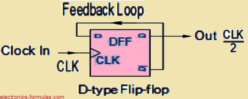
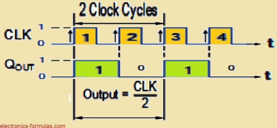
Looking at the timing diagrams we see that the “Q” output waveform has a frequency thats exactly half of the clock input. This means the flip-flop acts like a frequency divider.
If we add another D-type flip-flop we can make the output from the first “Q” the input for the second DFF.
The output from this second DFF will then be a quarter of the clock input frequency. We can keep going from there.
Basically with “n” number of flip-flops, we divide the output frequency by 2 raised to the power of n, in steps of 2.
This method of frequency division is super useful for sequential counting circuits. For instance if we start with a 60Hz mains frequency signal, we could reduce it down to a 1Hz timing signal using a divide-by-60 counter.
Alternatively if we use a divide-by-6 counter first, that would drop the 60Hz to 10Hz. Then we could feed that into a divide-by-10 counter to get down to a 1Hz timing signal or pulse.
MOD-4 Counter
Now technically speaking, we can think of a single flip-flop as not just a 1-bit storage device but also as a MOD-2 counter. It has one output that counts two states, either 0 or 1 when we apply the clock signal.
However, on its own, a single flip-flop has a limited counting sequence. By chaining more flip-flops together, we can boost our counting capacity and create a MOD counter for any value.
If we consider one flip-flop as a MOD-2 counter, then adding another one gives us a MOD-4 counter. This allows us to count in four distinct steps.
In this case we are effectively dividing the original clock input signal by four.
Then the binary sequence for this 2-bit MOD-4 counter would look like this: 00, 01, 10, and 11.
Analyzing the MOD-4 Counter and Timing Diagram


Just a heads up. For simplicity’s sake we have shown the switching transitions of QA QB and CLK in the timing diagram as happening at the same time.
This setup is for an asynchronous counter. In reality there is a tiny delay between when the positive clock (CLK) signal is applied and when the outputs at QA and QB change.
We can visually demonstrate how this 2-bit asynchronous counter works. For this, we can use a truth table and a state diagram.
| Clock Pulse | Present State | Next State | State Diagram | |||
| QB | QA | QB | QA | As shown below: | ||
| 0 (start) | 0 | 0 | ⇒ | 0 | 1 | |
| 1 | 0 | 1 | ⇒ | 1 | 0 | |
| 2 | 1 | 0 | ⇒ | 1 | 1 | |
| 3 | 1 | 1 | ⇒ | 0 | 0 | |
| 4 (repeat) | 0 | 0 | ⇒ | 0 | 1 | |
State Diagram
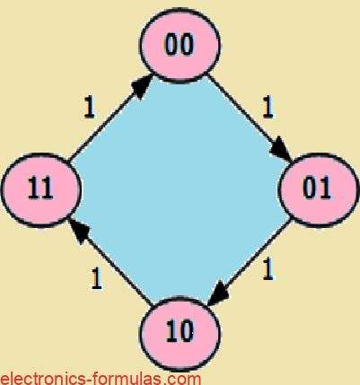
So if we check out the truth table for the counter and look at the values of QA and QB, we notice that when QA is 0 and QB is 0, the count is 00.
After we apply a clock pulse, QA changes to 1 and QB stays at 0, giving us a count of 01. With the next clock pulse, the values switch to QA = 0 and QB = 1 resulting in a count of 10.
Finally we get QA = 1 and QB = 1 which means the count is now 11. After another clock pulse, we loop back to 00 and from there we keep counting up in a binary sequence, 00, 01, 10, 11, and then back to 00 again.
Now when we look at a MOD-2 counter, it has just one flip-flop. If we step it up to a MOD-4 counter, it requires two flip-flops so it can count in four distinct steps.
If we want to take it further we can easily add another flip-flop to our MOD-4 counter to create a MOD-8 counter. This gives us a binary counting sequence of 2^3, counting from 000 up to 111 before resetting back to 000.
And if we add a fourth flip-flop, we get a MOD-16 counter. We can keep going and add as many flip-flops as we want!
Understanding the MOD-8 Counter and its State Diagram
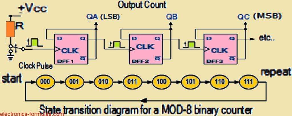
So we may build mod counters with a natural count of 2n states, producing counters with mod counts of 2, 4, 8, 16, and so on before they repeat.
However there are situations when a modulus counter that does not have a modulo that is a power of two is required, and will reset its count back to zero during the regular counting procedure. Imagine a counter with a modulus of 3, 5, 6, or 10, for examples.
Understanding Counters of Modulo “m”
So when we look at counters, whether they are synchronous or asynchronous, they each tick up one count at a time in a binary way. This means that an “n”-bit counter naturally acts like a modulo 2n counter.
But we can actually build mod counters to count to any number we want by using some external logic gates. These gates let us skip certain output states and stop at any count, resetting the counter back to zero, which means all flip-flops will have Q = 0.
Now with modulo “m” counters they do not go through all their possible states, instead, they count up to “m” and then reset to zero. It’s important to remember that “m” is always less than 2n (m < 2n). So how do we get a binary counter to reset to zero partway through its counting?
Luckily, counters can do more than just count up or down, they also have extra inputs called CLEAR and PRESET. These inputs let us clear the count back to zero (where all Q = 0) or set the counter to an initial value. For example, the TTL 74LS74 has active-low Preset and Clear inputs.
Let us keep it simple and say we connect all the CLEAR inputs together as active-high inputs. This way the flip-flops work normally when the Clear input is LOW (0). But when the Clear input is HIGH (1), the next positive edge of the clock signal will reset all the flip-flops to Q = 0, no matter what the next clock signal says.
Also since all the Clear inputs are linked together we can use just one pulse to reset all the outputs (Q) of the flip-flops to zero before we start counting.
This ensures that our count starts from zero. Plus some larger bit counters come with an extra ENABLE or INHIBIT input pin. This lets us pause the counting at any point in the cycle and hold that state until we decide to continue counting again.
So basically we can stop and start counting whenever we want without having to reset everything back to zero!
Modulo-5 Mod Counters
So if we want to design a MOD-5 counter, how do we go about it? First off we know that “m = 5” which means 2n has to be greater than 5.
Looking at the powers of 2 we see that 2^1 = 2, 2^2 = 4, and 2^3 = 8. Since 8 is greater than 5 we will need at least three flip-flops (N = 3) to get a natural binary count from 000 to 111 (which is 0 to 7 in decimal).
Now using the MOD-8 counter example we just mentioned, the truth table for its natural count will look like this:
Checking out the MOD-8 Counter and Truth Table

Truth Table
| Count | QC | QB | QA |
|---|---|---|---|
| 1 | 0 | 0 | 0 |
| 2 | 0 | 0 | 1 |
| 3 | 0 | 1 | 0 |
| 4 | 0 | 1 | 1 |
| 5 | 1 | 0 | 0 |
| 6 | 1 | 0 | 1 |
| 7 | 1 | 1 | 0 |
| 8 | 1 | 1 | 1 |
So since we want to build a MOD-5 counter, we need to tweak that 3-bit counter circuit a bit so it resets back to zero after counting up to 5. This means our counting sequence will go like this:
1→2→3→4→5→reset and then it starts over. A MOD-5 counter will give us a 3-bit binary count from 0 to 4, where 000 is a valid count state. So, our binary count sequence will look like this: 000, 001, 010, 011, and 100.
That means we need the counter circuit to reset itself because the next count which is six would result in an output of QA = 1, QB = 0, and QC = 1 in binary. We can see this in the state diagram that follows.
Analyzing Count Sequence of MOD-5
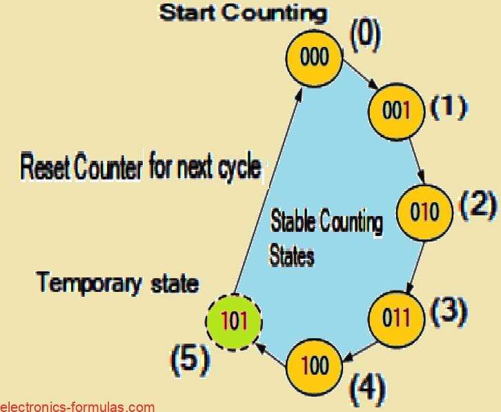
Here is how we can decode the output state of 101 (5) to generate a signal that clears (Clr) the counter back to zero.
We will do this using a 3-input AND gate (TTL 74LS11) and an inverter or NOT gate (TTL 74LS04). The inputs of our combinational logic circuit—made up of the inverter and the digital logic AND gate—are connected to the 3-bit counter outputs: QA, QB, and QC.

The 3-input AND gate will output a logic level “0” (LOW) for any input combinations other than the specific sequence we are targeting.
In binary the output sequence count appears as: 000, 001, 010, 011, 100.
Although it seems the counter counts up to the 101 state, as soon as the asynchronous sequence hits the binary state 101 (5), our combinational decoding circuit detects this condition.
The AND gate then produces a logic level “1” (HIGH) output which resets the counter back to zero. This means the counter stays in the 101 state for only a few nanoseconds before resetting to 000.
Using the input decoding of the AND gate, we reset the counter after it reaches a decimal count of 5, effectively creating the MOD-5 counter we need. When the decoding circuits output is LOW then it does not interfere with the counting sequence.
Understanding Modulus 5 Mod Counters and its Truth Table

We can use combinational logic decoding circuits along with a basic counter, whether it is synchronous or asynchronous, to create any desired type of MOD counter.
By decoding the distinct output states of the counter we can reset it at the specified count.
Take the simple MOD-5 example above, here we have used a 3-input AND gate to decode the binary output state of 101. Of course any logic circuit can be designed to reset the flip-flops at the required count.

That said, there is a drawback to using asynchronous counters for generating MOD counters of various sizes, they can produce “glitches” when the counter reaches its reset condition. In this brief moment, the counter outputs might show an incorrect value.
To avoid this we usually prefer synchronous counters for modulo-m applications, as all flip-flops are triggered by the same clock signal, ensuring they change state simultaneously.
Analyzing Modulus 10 Mod Counters
A great example of a modulo-m counter circuit that uses external combinational circuits to achieve a modulus of 10 is the Decade Counter.
Decade counters like the TTL 74LS90 have 10 distinct states in their counting sequence making them perfect for applications involving human interaction, especially when a digital display is needed.
With the decade counter we get four outputs representing a 4-bit binary number.
By adding external AND and OR gates we can identify the 9th counting state and reset the counter to zero.
Like other modulo counters, it sequentially accepts input clock pulses and counts from 0 to 9 in a continuous loop.
When the count reaches 9 (1001 in binary) then counter resets to 0000 instead of continuing to 1010.
The basic design of a decade counter can be built using JK flip-flops (TTL 74LS73) which change state on the negative trailing edge of the clock signal, as shown.
Diagram for the MOD-10 Decade Counter

Conclusions
In this tutorial about MOD Counters we learned how binary counters are unique circuits that generate sequences of bits driven by a clock signal.
We saw that the current state of a binary counter is determined by the combination of all its outputs.
The total number of distinct states a counter can cycle through is known as its modulo or modulus. A mod-n counter also called a divide-by-n counter, represents the total unique states it processes in one complete counting cycle.
We learned that the modulus of a counter is calculated using the formula 2^n, where n represents the number of flip-flops.
For instance a counter with 3 flip-flops can handle 2^3 = 8 unique states making it a MOD-8 counter. The highest binary number it can count is 2^n – 1 which means it counts from 0 to 7 (or 111 in binary).
Some common MOD counters include those with MOD values like 2, 4, 8, and 16.
With additional circuits we can configure these counters to count to other specific values, although their maximum modulus remains 2^n.
By using different numbers of flip-flops we can create a wide range of MOD counters.
One popular modulus for counters that do not count all the way up is ten (1010) known as MOD-10.
A counter with ten states is called a decade counter and works perfectly with digital displays. Other examples are MOD-6 and MOD-12 counters which are commonly used in digital clocks to display time.
References:
Leave a Reply