So when we think about amplifiers we usually picture those audio amplifiers that we come across in our stereos, CD players and radios which we have set up in our homes. In this part where we are investigating amplifiers, we took a closer look at just one type of amplifier circuit, specifically the single bipolar transistor amplifier. But it is worth noting that there is actually a whole bunch of different transistor amplifier circuit types which we can totally use!
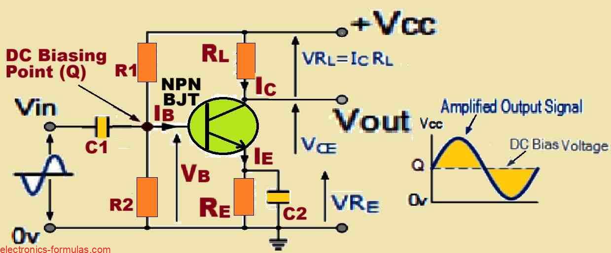
Standard Single BJT Stage Amplifier Circuit
Summarizing Small Signal Amplifier Circuits
Ok, let us now talk about Small Signal Amplifiers which we often refer to as Voltage Amplifiers. These Voltage Amplifiers have three main characteristics which we really need to keep in mind: Input Resistance, Output Resistance, and Gain.
Now when we talk about the Gain of a small signal amplifier, we are essentially discussing how much the amplifier boosts or “amplifies” the input signal.
Gain is actually just a ratio of the output compared to the input, which means it does not have any specific units attached to it.
We use the symbol (A) to represent it and there are a few common types of transistor gain which we come across: Voltage Gain (Av), Current Gain (Ai), and Power Gain (Ap).
Speaking of Power Gain, we can also express that in Decibels which we often shorthand to dB.
Now if we want to make sure that all of our input signal is amplified without any distortion in a Class A type amplifier, we have to use something called DC Base Biasing.
This DC Bias is important because it sets the Q-point of our amplifier right in the middle along the load line.
It is interesting to note that this DC Base Biasing means our amplifier is actually using up power even when there is no input signal coming in!
Since the transistor amplifier is non-linear, if we do not set the bias correctly then it can lead to some pretty significant distortion in the output waveform.
If our input signal is too large, we will see even more distortion because of clipping which is just another way of saying we are experiencing amplitude distortion.
If we do not position the Q-point correctly on the load line then we might end up with either Saturation Clipping or Cut-off Clipping which is not ideal at all!
Now when it comes to configurations, the Common Emitter Amplifier setup is by far the most widely used form of general-purpose voltage amplifier circuit which utilizes a Bipolar Junction Transistor.
On the flip side if we are working with a Junction Field Effect Transistor then the Common Source Amplifier configuration takes the crown as the most common general-purpose voltage amplifier circuit.
Table Comparing BJT Amplifiers with JFET Amplifiers
| Parameter | Common Emitter Amplifier | Common Source Amplifier |
| Voltage Gain, ( AV ) | Medium/High | Medium/High |
| Current Gain, ( Ai ) | High | Very High |
| Power Gain, ( AP ) | High | Very High |
| Input Resistance, ( Rin ) | Medium | Very High |
| Output Resistance, ( Rout ) | Medium/High | Medium/High |
| Phase Shift | 180o | 180o |
Summarizing Large Signal Amplifier Circuits
Talking of Large Signal Amplifiers which we often refer to as Power Amplifiers. These nifty devices can be broken down into various classes, each with its own unique characteristics.
Classifications of Power Amplifiers
Class A Amplifiers: In this category the output device is always conducting throughout the entire input cycle. This means they are always “on” which is why we see them as the most common type of power amplifier. But they come with a downside, they typically have an efficiency rating of less than 40%.
Class B Amplifiers: Now when we look at Class B amplifiers, these devices conduct for just 50% of the input cycle which makes them more efficient than Class A amplifiers, boasting around 70% efficiency. But they tend to produce a lot of distortion.
Class AB Amplifiers: Then we have Class AB amplifiers which sit somewhere in between. They conduct for more than 50% but less than 100% of the input cycle. This class aims to strike a balance between efficiency and sound quality.
The Ideal Power Amplifier
In an ideal world, a Power Amplifier is supposed to deliver a whopping 100% of the available DC power to the load. But that can be only in the dreams!
Efficiency and Distortion
While Class A amplifiers may be popular, their low efficiency can be a real nuisance. On the flip side the Class B amplifiers shine in efficiency but struggles with distortion issues.
Interestingly, Class B amplifiers are pretty good at conserving power when there is no input signal, definitely that is a plus!
Tackling Distortion
To tackle distortion in these Class B amplifiers, we can use a “Push-pull” output stage configuration which helps to significantly reduce it.
But we should keep in mind that simple push-pull Class B power amplifiers can still suffer from high levels of Crossover Distortion due to their cut-off point biasing.
Solutions for Crossover Distortion
To combat this pesky crossover distortion we can employ pre-biasing resistors or diodes, these little helpers can make a big difference!
Additionally we can build Class B Power Amplifiers using either Transformers or Complementary Transistors in their output stage.
References:
Leave a Reply