Nortons Theorem, like Thevenin’s Theorem, offers a technique for streamlining complex circuits. It enables us to swap out complicated circuits with much simpler equivalents that just require one resistor and one source of current or voltage. This equivalent circuit is made up of,
- A single current source (Is): The whole current output behavior of the original circuit is represented by this source.
- A single resistor (Rs): As viewed from the external connection points, this resistor reflects the whole resistance of the original circuit.
In basic terms, Norton’s Theorem reduces a complicated network of wires, resistors, and current sources, to only a parallel connection between a current source and a resistor..
The main idea is: This equivalent circuit with Rs and Is can be used in place of the original circuit from the viewpoint of an external load resistor (RL).
By “looking back” into the original circuit, and measuring the overall resistance with each current source open circuited (i.e. with their current flow halted), the value of Rs may be found.
The short circuit current measured at the original circuits output terminals without a load applied is known as the Norton current (RL is open).
Norton Equivalent Circuit

The Norton current (Is) represents the current that would flow through a short circuit at the output terminals. To find it, we calculate the Thevenin resistance (Rs) and then short the output while all current sources are open.
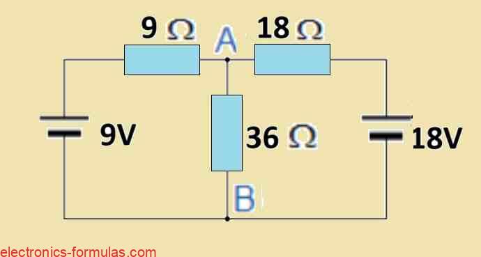
Consider, for instance, the circuit from the previous part that you are all familiar with.

First we need to take off the 36 Ω load resistor in the middle and short out terminals A and B to obtain the Norton’s equivalent of the circuit above.

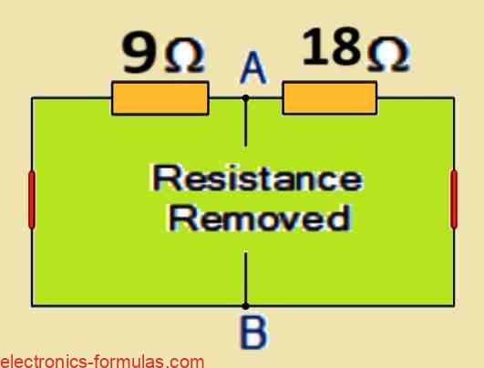
Short-circuiting terminals A and B causes the two resistors to be effectively linked in parallel across their respective voltage sources. As a result, current flow has a single, lower-resistance route.
With this updated setup, we can calculate:
- The current that travels through every resistor separately.
- The total amount of short-circuit current that occurs when A and B are shorted through the combined route.
When we Short Circuit Pints A and B:
I1 = 9 V / 9 Ω = 1 amp,
I2 = 18 V / 18 Ω = 1 amp,
Hence, Ishort-circuit = I1 + I2 = 2 amps
The two resistors are now functionally linked in parallel once we short out the two voltage sources and open circuit terminals A and B.
By figuring out the total resistance at terminals A and B, we can determine the value of the internal resistor Rs and obtain the circuit shown below.

Calculating the Equivalent Resistance (Rs)
Connecting 9 Ω resistor parallel with 18 Ω resistor:
RT = R1 * R2 / R1 + R2
= 18 * 9 / 18 + 9
= 6 Ω
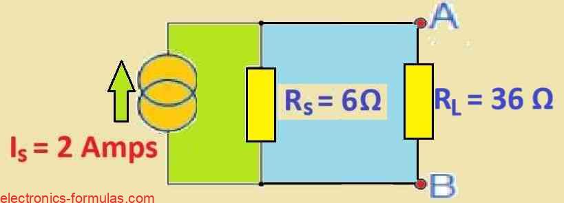
After determining the short circuit current (Is) and equivalent internal resistance (Rs), we can construct the Norton’s equivalent circuit shown below.
Norton’s Theorem Equivalent Circuit

After identifying the Thevenin/Norton equivalent circuit, we proceed to evaluate the original circuit (see the figure below) with the 36 Ω load resistor reconnected across terminals A and B.

As before, the two resistors are connected in parallel between terminals A and B, providing us with a total resistance of:
RT = R1 * R2 / R1 + R2
= 6 * 36 / 6 + 36
= 5.14 Ω
Upon connecting the load resistor, the voltage between terminals A and B is as follows:
VA-B = I * R
= 2 * 5.14
= 10.28 V
The current that is then flowing via the 36 Ω load resistor is as follows:
I = V / R
= 10.28 / 36
= 0.286 amps
It’s interesting to note that when we use Norton’s Theorem to get the current I3, the result is identical to the value (0.286 amps) that we previously got using Kirchhoff’s Current Law.
Conclusion
Like Thevenin’s Theorem, Norton’s Theorem provides another effective tool for circuit analysis. The main stages involved are broken out as follows:
Making the Circuit Simpler:
Isolating the Load: To start, take off the component you want to analyze or the load resistor (RL).
Discovering the Resistance of Thevenin (Wait, Thevenin’s?): Surprisingly, Norton’s Theorem makes use of Thevenin’s equivalent resistance (Rs) idea. By cutting off all sources of voltage and all sources of current in the original circuit, we may obtain Rs. The total resistance is effectively calculated “looking back” from the connecting sites (A and B).
Finding Norton Current (Is): After deactivating all current sources, attach a shorting link between terminals A and B. A route with zero resistance is therefore created. The current flowing via this short circuit is known as the Norton current (Is).
Evaluating the Load
Replacing the original load resistor (RL) between terminals A and B completes the process of reconnecting the load.
Current Through the Load: Using this basic equivalent circuit, which has a current source and a resistor connected in parallel, you can identify Rs and Is and then use them to assess the current passing through the load resistor (RL).
The next tutorial is going to look into the Maximum Power Transfer Theorem. In order to transmit the maximum amount of power from the source to the load in a circuit, this theorem assists in determining the ideal load resistance. When examining linear circuits with varying loads, both simple and complicated, this theory is especially helpful.
References: Norton’s theorem
Leave a Reply