Although the fundamental filtering mechanism continues to be the same as in the passive RC filter, the active high-pass filter (HPF) integrates an operational amplifier (op-amp) to provide some essential characteristics.
Gain & Control:
The op-amp amplifies and controls the gain response of the filter. This is a huge benefit over passive high-pass filters, which have no gain control by design.
Simple Design Procedure:
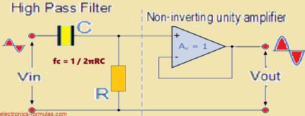
Much like the low-pass filter scenario, the simplest active HPF arrangement consists of cascading a normal inverting or non-inverting op-amp stage with a basic RC high-pass passive filter circuit, as shown below. This method takes use of the RC networks filtering qualities while also maximizing the gain capabilities of the op-amp.
First Order High Pass Filter Circuit
Bandwidth Limitation:
However it is necessary to recognize an important restriction of active HPFs. Unlike passive high-pass filters which have a theoretically limitless passband frequency response, active HPFs are constrained by the op-amp’s open-loop characteristics, especially its bandwidth.
The Effects of Op-Amp Bandwidth:
The active HPF’s maximum operational frequency will be restricted by the op-amp’s finite bandwidth, which has been designated as the Gain-Bandwidth Product (GBWP) or the open-loop voltage gain (AVOL). This constraint causes a roll-off in the filter’s gain response at higher frequencies. In simple terms the closed-loop response of the op-amp within the filter circuit ultimately overlaps with its open-loop response, resulting in a loss of gain at higher frequencies.
The Effective Bandpassing Behavior:
Because of this bandwidth limitation, active HPFs could appear to function as bandpass filters, having a high-frequency cut-off dictated by the op-amp and its gain settings. Although the ideal high-pass response is infinite in the passband, the actual restrictions of the op-amp cause a roll-off at higher frequencies.
Selection Considerations:
Therefore when you are constructing active HPFs, great attention should be paid to the op-amp’s GBWP and AVOL requirements. Selecting an op-amp with a GBWP that is much higher than the filter’s target cut-off frequency helps to mitigate the influence of this constraint and produce a response nearer to the optimal high-pass characteristic.
The Effect of Op-Amp Open-Loop Gain on Active Filter Performance.
The µA741 which is a typical operational amplifier (op-amp), demonstrates how op-amp characteristics can restrict the active filter performance.
µA741 Characteristics:
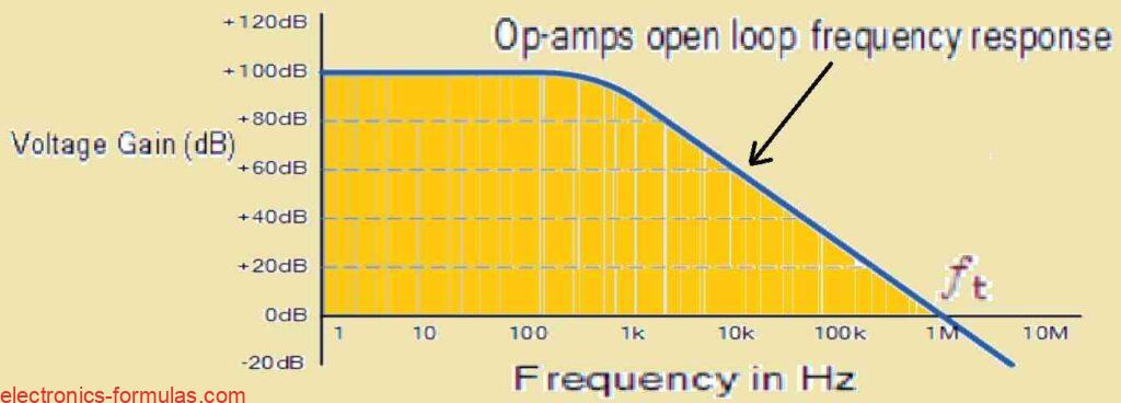
The µA741 has a typical open-loop DC voltage gain (AVOL) of roughly 100 dB, however it rolls off at a rate of -20 dB/decade (-6 dB/octave) as frequency increases. The roll-off keeps going until the gain approaches unity (0 dB) at the transition frequency (fT), which for the µA741 is around 1 MHz.
Equivalent low-pass response:
The µA741s frequency response is similar to a first-order low-pass filter because of its gain roll-off characteristic. This tendency can often be seen in frequency response curves, as shown below.
An example of a typical operational amplifier’s frequency response curve:
High-Pass Filters’ Bandwidth Limitation:
This open-loop gain characteristic limits the effectiveness of active high-pass filters at high frequencies. The open-loop amplifier’s total bandwidth is primarily determined by the unity-gain crossover frequency (fT), which limits the active HPF’s high-frequency response.
Filter Performance and Gain-Bandwidth Product (GBWP)
The gain-bandwidth product (GBWP) of the op-amp is very important. This product generally varies in frequency from 100 kHz for small-signal amplifiers to 1 GHz for high-speed digital video amplifiers. Although active filters built around op-amps may achieve high precision and performance, they require low-tolerance resistors and capacitors.
Practical Filter Design Considerations:
In most realistic cases, the intended maximum passband frequency for a closed-loop active high-pass or bandpass filter is significantly lower than the op-amp’s maximum open-loop transition frequency. But while designing active filter circuits, it is vital to choose a suitable op-amp. Inadequate consideration of the op-amps frequency response characteristics could end up in the loss of high-frequency signals, thereby causing signal distortion in the filter.
Using an op-amp with a GBWP that is significantly higher than the filter’s planned cut-off frequency assists in eliminating this constraint and enables the filter to obtain a response nearer to the optimal high-pass or bandpass characteristic.
Amplification Response of a First-order Non-inverting Active High-Pass Filter (HPF) Circuit.
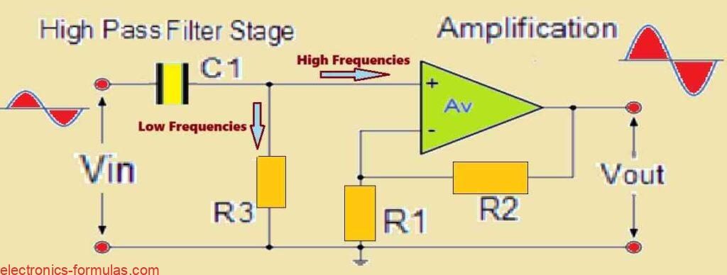
The circuit shown is a first-order (single-pole), non-inverting active high-pass filter (HPF). This filter attenuates low-frequency frequencies although allowing high-frequency signals to flow through with amplification.
Operational Breakdown as follows:
The design concept is clear. The circuit contains a couple of cascaded stages:
Passive High-Pass Filter Section: The first stage comprises a passive RC high-pass filter network. This largely controls the filter’s cut-off frequency (fC) and roll-off rate in the stopband (usually -20 dB/decade).
Non-Inverting Amplifier Stage: After the passive filter section, a non-inverting operational amplifier (op-amp) is introduced. This op-amp stage delivers two main functionality:
Amplification: It boosts the signal that has been fed through the passive filter portion. The gain of this stage is governed by the feedback resistor (R2) to input resistor (R1) ratio, which is given in the formula Av = 1 + (R2 / R1).
Non-Inverting Output: Because of the non-inverting design, the output signal has the same phase as the input signal of the op-amp
The frequency response:
This active HPF’s overall frequency response is quite similar to that of the passive high-pass filter component before it. But there is a crucial difference: the amplitude of the signal is increased by the gain (Av) given by the non-inverting op amp stage.
The Design factors to consider:
When you are designing this sort of active HPF, it is critical to choose proper component values (resistors and capacitors) for the passive filter section in order to achieve the specified cut-off frequency and roll-off rate. Likewise, the R1 and R2 values are used to determine the filter’s necessary gain (Av).
Formula for Calculating Gain for an Active High Pass Filter
Voltage Gain Av = Vout / Vin = AF (f / fc) / {√[(1 + (f / fc)2]}
- In the above formula:
- AF represents the Pass band Gain of the filter, ( 1 + R2/R1 )
- f denotes the Frequency of the Input Signal in Hertz, (Hz)
- fc refers to the Cut-off Frequency in Hertz, (Hz)
Similar to the low pass filter, the high pass active filter’s functionality may be confirmed using the above shown frequency gain formula, in the following manner:
- At very low frequencies, f < fc, Vout / Vin < AF
- At the cut-off frequency, f = fc, Vout / Vin = AF / √2 = 0.707 AF
- At very high frequencies, f > fc, Vout / Vin ≅ AF
From the above information we understand that when the frequency rises, the Active High Pass Filter’s gain AF rises from 0 Hz to the low frequency cut-off point f̒C, at the rate of 20 dB/decade. The gain of the filter is 0.707*AF at f̒C. Below this cut-off frequency fC, all frequencies are pass band frequencies resulting in a constant gain of AF. The op-amp’s closed loop bandwidth determines the maximum frequency.
While working with filter circuits, the quantity of the circuit’s pass band gain is often specified in decibels (dB) as a function of the voltage gain, which is defined as:
Voltage Gain Magnitude Expressed in (dB)
Av(dB) = 20log10(Vout / Vin)
∴ -3dB = 20log10[0.707(Vout / Vin)]
First-Order Active High-Pass Filter (HPF) Response and Design.
When using first-order filters, we see a typical 20 dB/decade (or 6 dB/octave) rise in the frequency response curve up to the cut-off frequency (fC). This cut-off point continues to be at -3 dB from the highest gain value. Fortunately, the formula for obtaining the lower cut-off frequency (fC) is exactly the same as for previous filter circuits, as we can find below:
fC = 1 / (2πfRC) Hz
The phase angle, or phase shift, of the output signal is the same as that of the passive RC filter, and it leads the input. At the cut-off frequency (fC), the phase shift reaches +45°. In order to calculate the phase shift, we can use the following given formula:
Phase Shift (Φ) = tan-1 (1/(2πfRC)).
It is worth noting that a basic first-order active High Pass Filter HPF may also be built by using an inverting operational amplifier arrangement. An example circuit design with a suitable frequency response curve is shown below. For this particular case, a gain of 40 dB has been considered. (Insert the circuit schematic here).
Inverting Operational Amplifier Circuit

Frequency Response Curve for the above design:
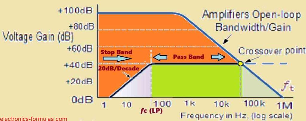
We must remember the following important points:
In this design we have employed a passive RC high-pass filter portion, coupled by an inverting op-amp stage.
The opamp adds amplification (as seen in the example) and inverts the output signal.
The cut-off frequency and roll-off rate can both be controlled by carefully adjusting component values in the passive filter section (R and C).
The required gain (Av) for the filter is determined by the R1 and R2 values used in the op-amp stage.
Solving an Active High Pass Filter Problem#1
Let’s Design a First-Order Active High-Pass Filter
We want to design a first-order active high-pass filter with the following specific set of parameters:
- Passband gain (Av): 2
- Cut-off frequency (fC): 10 kHz
- Input capacitor (C): 100 nF
Our goal is to calculate the values for:
- The cut-off frequency determining resistor (R)
- The gain resistors in the feedback network (assuming a standard inverting or non-inverting amplifier configuration)
Additionally, we want to plot the expected frequency response of the filter.
Step 1: Let us find the Cut-Off Frequency Resistor (R)
We know the formula for the cut-off frequency (fC) of a first-order high-pass filter:
fC = 1 / (2 * π * R * C)
We can rearrange this formula to solve for R:
R = 1 / (2 * π * fC * C)
Substituting the known values inside the above formula we get:
R = 1 / (2 * π * 10 kHz * 100 nF)
- Here we need to convert nanoFarads (nF) to Farads (F) for the calculation: 10 nF = 10 x 10-9 F
- We also need to convert kHz to Hz: 10 kHz = 10,000 Hz
- Therefore: R = 1 / (2 * π * 10000 * 100 x 10-9)
- Solving the above we get R ≈ 159.15 Ω approximately, or maybe around 160 Ω.
Calculating gain resistors for a first-order active HPF.
We must now calculate the gain resistor values (R1 and R2) in our first-order active high-pass filter’s feedback network. Our objective for passband gain (AF) is set at 2.
Because we’ll be most likely utilizing a typical inverting or non-inverting amplifier arrangement, the formula for the relationship between gain resistors and gain is:
AF = 1 + (R2 / R1).
In the above example, we would like a gain of two (AF = 2). When we input this into the formula and evaluating the ratio of R2 to R1, we get:
2 = 1 + (R2 / R1)
(R2 / R1) = 1
This indicates us that R2 must be equal to R1 for a gain of 2. As a result, we can easily select the identical value for both resistors.
For the sake of simplicity, we will use a standard value of 10 kΩ for each feedback resistor (R1 = R2 = 10 kΩ).
Remember these Key Takeaways:
The feedback resistor value of 10 kΩ is arbitrary and could be altered depending on practical considerations, such as available resistor values or biasing needs in the op-amp circuit.
Remember to check that the selected R1 and R2 values meet the intended gain criteria.
To acquire the data for the frequency response bode plot, we can simply substitute the values obtained above across a frequency range of 100Hz to 100kHz into the below given voltage gain equation:
Voltage Gain Av = Vout / Vin = AF (f / fc) / {√[(1 + (f / fc)2]}
Thus, we subsequently get the data table which is shown below:
| Frequency, ƒ ( Hz ) | Voltage Gain ( Vo / Vin ) | Gain, (dB) 20log( Vo / Vin ) |
| 100 | 0.20 | -14.02 |
| 200 | 0.39 | -8.13 |
| 500 | 0.89 | -0.97 |
| 800 | 1.25 | 1.93 |
| 1,000 | 1.41 | 3.01 |
| 3,000 | 1.90 | 5.56 |
| 5,000 | 1.96 | 5.85 |
| 10,000 | 1.99 | 5.98 |
| 50,000 | 2.00 | 6.02 |
| 100,000 | 2.00 | 6.02 |
Analysis of the Active HPF using Bode Plots
Since now we have the frequency response data from the above table, we can display it with a Bode plot.
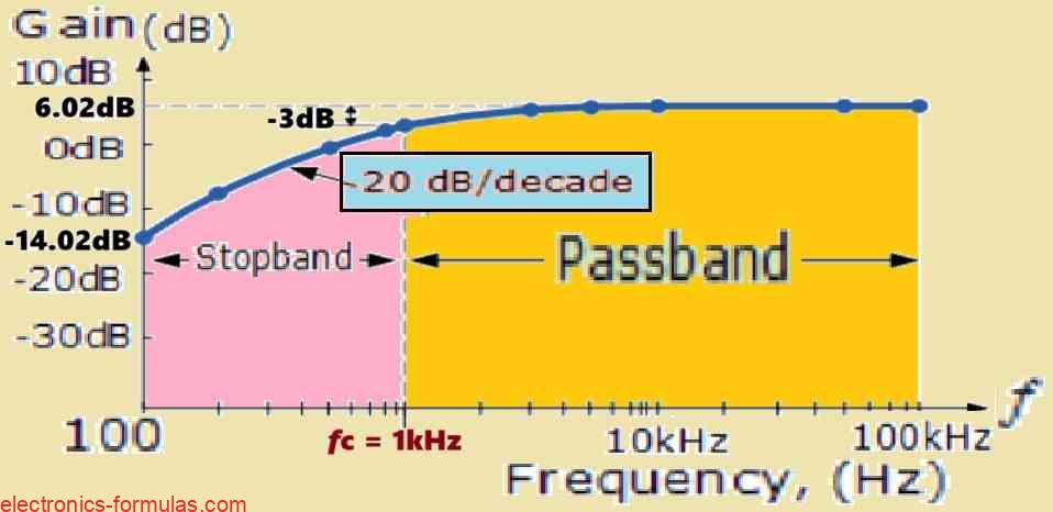
Stopband Response (100Hz-1kHz):
Throughout the stopband which extends from 100 Hz to 1 kHz, the gain increases at a rate of 20 dB per decade. This result coincides with the anticipated roll-off of a first-order high-pass filter in the stopband.
Passband response (above one kHz):
Above the 1 kHz cut-off frequency (fC), the gain approaches the passband. In an ideal world the gain should remain constant at the intended value (in this example, 6.02 dB). But as previously stated, the open-loop bandwidth restriction of the operational amplifier comes into play.
The Effect of Op-Amp Bandwidth:
The op-amp’s limiting open-loop bandwidth inhibits the filter’s ability to maintain a perfectly flat gain response in the passband at higher frequencies. As frequency increases in the passband, the op-amp’s gain begins to roll off, resulting in an apparent deviation from the ideal constant gain response as shown in the Bode plot.
Overall Bode Plot Shape:
The filter circuits Bode diagram reflects the following insights. It displays a 20 dB/decade roll-off in the stopband, followed by a somewhat flat zone around the cut-off frequency, and finally a steady roll-off in gain at higher frequencies due to the op-amp’s bandwidth limitations.
The Applications of Active High-Pass Filters
Active HPFs have various applications in audio circuits:
Audio Amplifiers and Equalizers: These kinds of filters could be strategically inserted into audio amplifier or equalizer circuits for controlling the high-frequency signals sent to tweeter speakers. This enables for more precise control of the audio system’s high-frequency response.
Speaker Systems – Low-Frequency Noise Reduction: Active HPFs may effectively remove or reduce low-frequency noise or “rumble” in speaker systems. This unwelcome interference might cause the degradation of the audio quality. The HPF contributes to the clarity and quality of music delivered by speakers by filtering out these low frequencies. In these circumstances the active HPF is frequently referred to as a “treble boost” filter highlighting its function in improving high-frequency response.
Second-Order Active High Pass Filter Circuit:
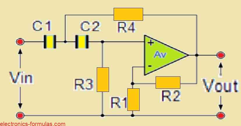
A first-order active HPF, just like a passive filter, can easily be converted into a second-order active HPF. This is accomplished by adding an extra RC network to the filter circuit’s input route.
The main advantage of a second-order HPF is its sharper roll-off feature in the stopband. A second-order HPF has a sharper roll-off of 40 dB/decade (or 12 dB/octave) than a first-order filter with a roll-off of 20 dB per decade. This steeper roll-off delivers a more noticeable attenuation of the undesired low-frequency sounds, giving you more control over how the filter responds.
Creating Higher-Order Active High-Pass Filters (HPFs)
Here we learn how to achieve higher-order active HPFs by cascading lower-order filter stages. Here, is a summary of the main concepts:
Cascading to Higher Orders:
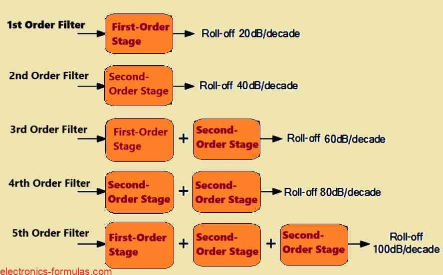
The primary approach is to strategically interconnect multiple first-order and/or second-order active HPF circuits in series. This cascaded technique enables the production of HPFs with even or odd filter orders (second, third, fourth, etc).
Even-Order Filters: For active HPFs with even orders (4th, 6th, etc), the cascaded design uses just second-order filter stages.
Odd-Order Filters: Active HPFs with odd orders (3rd, 5th, etc.) must start the cascading with a first-order filter stage, then proceed to successive second-order stages.
Order & Roll-Off:
It is crucial to remember that the order of the filter has a direct impact on its roll-off behavior in the stopband. Higher-order filters have steeper roll-off rates than lower-order filters. For example a second-order HPF includes a 40 dB/decade roll-off, but a first-order HPF comes with a 20 dB/decade roll-off.
Using cascaded active filter stages, we can produce HPFs with customized frequency responses that fit specific application needs.
How to Cascade Active High Pass Filter Circuits
Tradeoffs in Higher-Order Active HPFs
Although the article shows the feasibility of creating active HPFs with virtually infinite order by cascading lower-order stages, it is critical to note several practical considerations:
Higher Complexity and Size: When the filter order increases, the circuit complexity rises owing to the extra cascaded stages. This results in a bigger physical layout for the filter circuit on the PCB.
Limited Accuracy: One unexpected result of higher filter orders is a possible drop in accuracy. This presents itself as a difference between the actual stopband response and the ideal response estimated by the theoretical model. A number of factors might be contributing to this, particularly the component tolerance’s and non-ideal op-amp performance at higher frequencies.
Maintaining Uniform Cut-off Frequency:
The article makes an intriguing assessment: if all of the frequency determining resistors (R1, R2, R3, etc) and capacitors (C1, C2, C3, etc.) in a cascaded HPF design are selected to have the same value then the cut-off frequency (fC) becomes constant regardless of filter order. This streamlines the design process, by requiring simply to solve for the component values to reach the required cut-off frequency, followed by cascading phases.
Fixed Gain in Particular Circumstances:
But it is vital to remember that when all frequency-determining components are identical, the total gain of the higher-order filter would be fixed. This may limit the design’ s versatility if precise gain modifications are required inside the passband.
Looking Forward: Active Band-Pass Filters:
In the upcoming tutorial I will discuss the concept of active band-pass filters which are made by specifically cascading a high-pass and low-pass filter. This method enables the design of filters which individually pass a certain band of frequencies in the signal spectrum.
References: High-pass filter
3 dB cut-off frequency of first-order IIR high-pass filter
Leave a Reply