
An “Exclusive-NOR Gate” will work by combining the functionality of an Exclusive-OR (XOR) gate and a NOT gate, but you will find that its truth table looks similar to that of a standard NOR gate, because, as we see that its output is typically at logic level “1” and switches to logic level “0” whenever any of its inputs are at logic level “1.”
The output of an Exclusive-NOR gate will become “1” only when we apply both of its inputs with an identical logic levels, which can be either both “0” or both “1” (e.g., “00” or “11”). Then we can write the Boolean expression for this gate is as:
Q = (A ⊕ B) = A.B + A.B
I can explain this in simpler terms, here the output of an Exclusive-NOR gate will be “HIGH” whenever we make both of its inputs, A and B, at the same logic level, either “1” or “0”, meaning, if we apply an even number of “1s” across its input terminals then it will produce an output that will be logic “1”; otherwise, it will be logic “0.”
Because of this characteristic of producing a output of logic “1” when its inputs are applied with logically equivalent values, we find that the Exclusive-NOR gate is also sometimes referred to as an Equivalence Gate.
If you look at the logic symbol of an Exclusive-NOR gate you will see that the output of this gate carries an additional tiny circle which is also referred to as an “inversion bubble” (ο), which simply indicates the NOT operation of the gate. This functionality of an Exclusive-NOR gate causes it to be the complement or “inverse” of the Exclusive-OR gate (A ⊕ B) that we have already discussed in our previous lessons.
Equivalent of Ex-NOR Gate


We can also express the Exclusive-NOR Gate as “Ex-NOR” or “XNOR” function, which can be basically obtained by joining the standard types of gates with one another, and this gives rise to more complex types of gate functions. One example of this type of combined result can be witnessed below, as the a 2-input Exclusive-NOR gate:
Symbol and Truth Table of 2-input Exclusive NOR Gate
Symbol


Truth Table
| B | A | Q |
| 0 | 0 | 1 |
| 0 | 1 | 0 |
| 1 | 0 | 0 |
| 1 | 1 | 1 |
The Boolean Expression for the above gate is Q = A ⊕ B, we can read it as, if A AND B the SAME gives Q
Thus we get the Boolean expression of: Q = AB + AB
An Exclusive-NOR (Ex-NOR) gate will generate a high output (Q) whenever we apply both of its inputs, A and B, with identical logic level. It means that this gate acts like an ‘even function,’ which generates a high output only whenever we apply it with an even number of high inputs.
This appears to be just the opposite of an Exclusive-OR (Ex-OR) gate, in which the outputs become high only when we apply an odd number of high inputs. However unlike Ex-OR gate, the Ex-NOR gate will always produce a high output high when all of its inputs are subjected with a low logic level.
So, when an Ex-NOR gate contains more than two inputs, this gate is more commonly referred to as an ‘even function’ or ‘modulo-2-sum’ (Mod-2-SUM), rather than an Ex-NOR function, and we can extend this principle to any desired number of inputs, as we see it in a three-input Ex-NOR gate.
Symbol and Truth table of 3-input Exclusive NOR Gate
Symbol

Truth Table
| 0 | 0 | 0 | 1 |
| 0 | 0 | 1 | 0 |
| 0 | 1 | 0 | 0 |
| 0 | 1 | 1 | 1 |
| 1 | 0 | 0 | 0 |
| 1 | 0 | 1 | 1 |
| 1 | 1 | 0 | 1 |
| 1 | 1 | 1 | 0 |
The Boolean Expression for the above gate is Q = A ⊕ B ⊕ C, and we can read it as “any EVEN number of Inputs” gives Q
Thus we get the Boolean expression of: Q = ABC + ABC + ABC + ABC
In our earlier discussion we understood that the Ex-NOR function is implemented by using two types of basic logic gates such as Ex-OR and a NOT gate, and through the 2-input truth table as given above, also it is easy for us to extend the Ex-NOR function to: Q = A ⊕ B = (A.B) + (A.B). In simple terms it follows that we can simply create this new expression by implementing the gates as illustrated in the following diagram.
Equivalent Circuit of an Ex-NOR Gate


You will find that the high complexity involved in implementing an Exclusive-NOR (Ex-NOR) gate through AND, NOT, and OR gates appears to be an unfortunate drawback, but a simpler method could be to simply employ only our own NAND gates. You can easily accomplish this by interconnecting NAND gates in a precise arrangement to simulate the Ex-NOR function, as indicated below:
How to Implement Ex-NOR Function using NAND gates


We can find Ex-NOR gates being regularly employed in electronic circuits such as adders, subtractors, and parity checkers that are intended for arithmetic operations and data verification. Also, we can use the Ex-NOR gates to compare the values of binary digits or integers since it generates a high output whenever its inputs are applied with identical logic levels, and that is why the Ex-NOR gates tend to become a very useful part of digital comparator circuits.
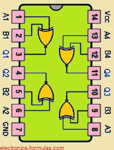
The digital logic Exclusive-NOR gate IC’s which are easily and readily procured from the local market are as listed in the following table:
| Logic Type | Part Number | Description |
|---|---|---|
| TTL Logic Ex-NOR Gates | 74LS266 | Quad 2-input |
| CMOS Logic Ex-NOR Gates | CD4077 | Quad 2-input |
Pinout Diagram of a common Quad 2-input Ex-NOR Gate IC 74266 is shown below:

In our next upcoming tutorial which involves the Digital Logic Gates, I will talk more about the digital Tri-state Buffer gate which may be also referred to as the non-inverting buffer gate, and I will show you how these can be implemented through both TTL and CMOS logic circuits. Additionally we will also learn about its Boolean Algebra definition and truth table.
References: XNOR gate