
In this post I will explain the Armstrong Oscillator which is yet another type of an LC oscillator circuit.
What makes this so special is that it uses a parallel resonator circuit to store energy and then switches that energy between its two primary elements, the inductor (L) and the capacitor (C).
The back-and-forth exchange of energy gives rise to a sine-wave output with a constant amplitude and frequency. The parallel LC resonator circuit fundamentally works as the heart of the Armstrong oscillator circuit.
Now as we already know, LC oscillators can be tuned to different frequencies using something called regenerative feedback.
That is just a fancy way of saying that the oscillator uses an amplifier with positive feedback to keep things going. You can tweak it to work across a range of frequencies which really looks handy.
But if you want to turn a basic amplifier into an actual oscillator, you would need to do something specific, meaning, we have to take some portion of the output signal from the amplifier circuit and then feed it back to its input.
This feedback is crucial because it is what gets the amplifier oscillating. The feedback has to be in-phase with the input signal which means that it needs to be a positive feedback signal.
And it also needs to be strong enough so that it is able to overcome any losses in the circuit and allow the oscillations to keep going indefinitely at the intended frequency we may want.
The Armstrong Oscillator, just like any other LC oscillator, is a “sinusoidal oscillator” or a “harmonic oscillator.”
It is designed to produce high-frequency sine waves which are mostly used in radio frequency (RF) applications.
These frequencies can range between just a few kilohertz (kHz) and all the way up to several hundred megahertz (MHz), which makes it perfect for circuits like radio transmitters or other wireless communication devices.
You will find that the main amplifier circuit in an Armstrong oscillator is usually built around a transistor, which can be either a Bipolar Junction Transistor (BJT) or a Field Effect Transistor (FET).
But here is an important thing that you must consider; when you are working with very high RF frequencies then you cannot just use any old transistor.
Regular small signal type, audio frequency BJTs or FETs will simply not going to work because they are not designed to handle high frequencies.
Instead, you need to use special high-frequency transistor models which are specifically made for RF applications to ensure that they are able to oscillate and switch rapidly.
Fundamental LC Circuit Feedback Configurations
The LC oscillators, which are built using a combination of inductors and capacitors, can be configured through the following three fundamental designs for enabling a feedback signal from the LC resonant tank circuit to operate an amplifier:
- Hartley Tapped Coil
- Colpitts Capacitance Divider
- Armstrong Transformer Tickler Coil
The respective diagrams can be seen below:

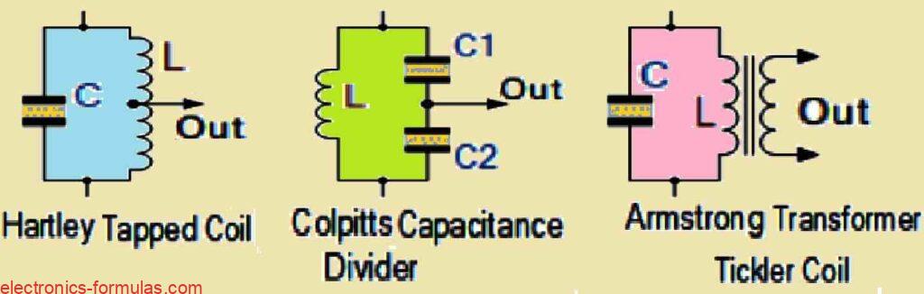
So, if we look at the Colpitts Oscillator, we can see that the feedback signal is taken from a point between two capacitors which together form what is called a capacitive voltage divider network.
This arrangement is what allows the feedback to flow back into the amplifier, keeping the oscillations going.
On the other hand the Hartley Oscillator does things a little differently. Instead of using capacitors, it pulls its feedback signal from a point between two inductors, or sometimes from a tap on a single inductor.
This creates an inductive voltage divider network which serves the same purpose as the capacitive one in the Colpitts setup, but it just uses inductors instead.
Now talking about the Armstrong Oscillator which gets its name from the engineer who invented it, Edwin Armstrong, this oscillator uses a unique component which is a high-frequency transformer.
The primary winding of this transformer is driven by the oscillator circuit itself and then the secondary winding takes care of two things, providing feedback and also delivering the output signal.
What is cool here is that the resonant circuit, which is still the heart of the oscillator, is coupled to the input via this transformer.
In this configuration, the positive feedback which the amplifier needs to keep oscillating is provided through the secondary coil of the transformer.
This secondary coil produces an out-of-phase signal (which is inverted), and this is exactly what’s we need to feed back into the amplifier and maintain those continuous oscillations.
Analyzing a Basic Armstrong Oscillator Design

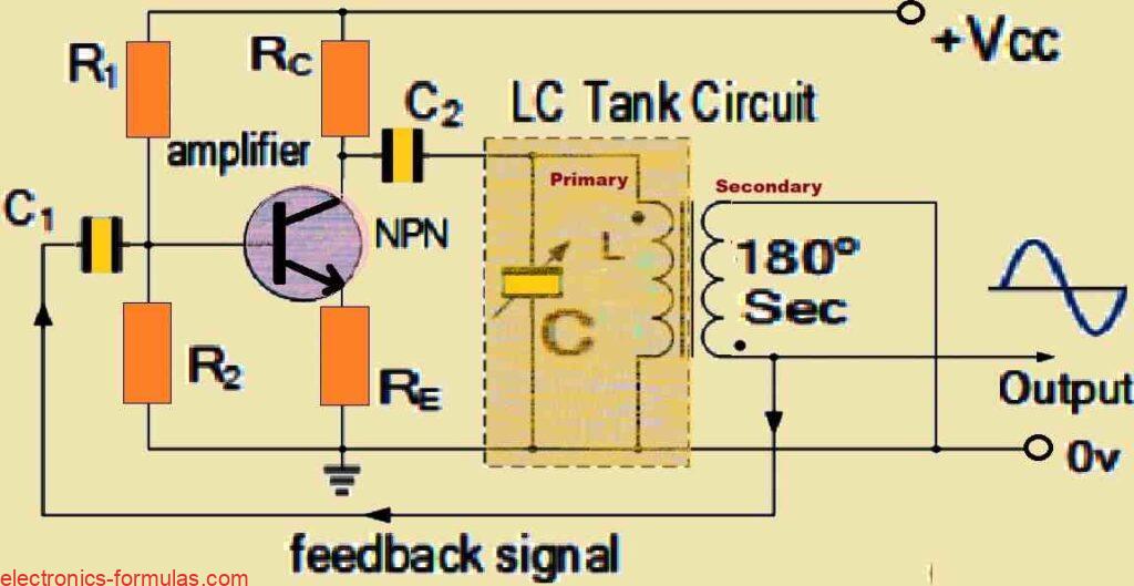
Next we will analyze how the Armstrong Oscillator works in this setup. Here, we have two resistors R1 and R2, which are connected in a voltage divider configuration.
Their job is to provide the base bias voltage (VB) which is needed for the base-emitter junction of the NPN transistor.
This ensures that the transistor stays in the right operating mode. Then there is the emitter resistor RE, which plays an important role in stabilizing the emitter bias.
What is great about this resistor is that you can actually change the output amplitude of the oscillator simply by adjusting the value of RE.
Now, the LC tank circuit which determines the frequency, acts as the load for the transistor and is connected to the collector output of the transistor.
This setup makes work like a tuned-collector oscillator. The primary winding of the transformer which has its own inductance (L), is connected between the collector and ground (0V).
Together with a capacitor (C), this primary winding forms a parallel resonant circuit and the values of these components determine the frequency of the oscillator.
The secondary winding of the transformer acts as the “feedback coil.” It is loosely coupled with the primary coil through the magnetic field, and this coil is responsible for providing the regenerative feedback which is needed to keep the oscillations going repeatedly, cycle after cycle.
As I mentioned earlier, the transformer is wound in such a way that the voltage induced in the secondary winding is 180 degrees out-of-phase with the voltage across the primary LC tank circuit.
This phase difference is very crucial because it means that the total phase shift around the circuit becomes zero, which is essential for sustaining the oscillations.
So, the inductance of the primary winding (LPRI) and the timing capacitor (C) together form the resonant circuit that ultimately decides the frequency of oscillation for the Armstrong oscillator.
The output frequency “fo”, of the tank circuit is calculated using the following formula:
Formula for Calculating Armstrong Oscillator Frequency
fo = 1/2π√(LC)]
So, since the LC oscillator needs a phase shift to achieve positive feedback, the phase difference between the primary and secondary windings of the transformer makes it the perfect component to use in the Armstrong oscillator design.
But there are some extra advantages that we get by using a transformer here.
1) Isolation: The transformer offers electrical separation between the feedback channel and the main resonant circuit, preventing direct interference and maintaining sustained oscillations.
2) Impedance Matching: The transformer also plays a role in matching the impedance between the LC resonant circuit and the input of the amplifying device. By matching the impedance, it ensures that energy is transferred efficiently between the stages which helps the oscillator to run smoothly.
3) Phase Shift: The transformer guarantees that the feedback signal is in the correct phase orientation to keep the oscillations going. The phase shift it provides is exactly what we need for getting the positive feedback in this kind of oscillator design.
Now instead of using a traditional transformer we could also use two separate wound coils that are inductively coupled to each other. In this kind of circuit design, the feedback comes from something called a “tickler coil” and we can control the amount of positive feedback by adjusting the mutual coupling (M) between the two coils.
Actually you could vary how close or far apart the coils are or you could tweak the number of turns in each coil to either strengthen or weaken the magnetic field between them.
When you are using a transformer, the mutual coupling is usually fixed since both coils are wound onto a common magnetic core. This core keeps the coupling steady, unlike with separate coils where you get more flexibility to adjust the feedback.
Solving an Armstrong Oscillator Circuit Problem
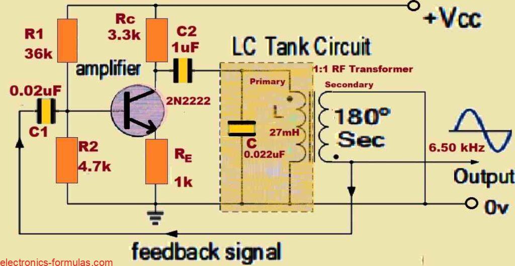
Let us consider the above shown circuit design of an Armstrong oscillator. Referring to this diagram let us calculate the output frequency of the oscillator if we assume the self-inductance of the primary winding of the transformer to be 27mH.
Using the standard formula:
fo = 1/2π√(LC)]
= 1/2π√(0.027 * 0.022 * 10-6)
= 6530 Hz or 6.50 kHz
So, from the calculations we realize that the frequency of oscillation for the above shown Armstrong oscillator circuit is around 6.50 kHz.
Conclusions
In this tutorial we have explored the Armstrong oscillator which is a type of LC oscillator used to generate periodic oscillating signals.
One of the things that makes the Armstrong oscillator so interesting is its relatively simple design and reliable performance, which is why it’s often used in various radio frequency (RF) transmitter and receiver applications.
We have learned that the Armstrong oscillator works using a transformer as part of its design, along with an amplifier stage.
The amplifier helps counteract any losses in the LC tank circuit, where energy alternates between being stored in the electric field of the capacitor and the magnetic field of the inductor. This process ensures that oscillations continue without dying out.
The transformer itself is made up of two coils, usually called the primary and secondary windings. These two coils are magnetically coupled, meaning that a signal in one coil (the primary) induces a signal in the other coil (the secondary).
The primary winding is part of the LC resonant circuit which includes both the inductor (L) and the capacitor (C) that set the oscillator’s frequency.
The secondary winding is responsible for providing the feedback signal to the input of the transistor amplifier. This feedback is “in-phase” with the original signal which is crucial for sustaining continuous oscillations.
In essence the transformer becomes the main component in the Armstrong oscillator’s operation. It controls the amount of feedback through the electromagnetic coupling between the feedback secondary coil and the main primary coil.
Beyond just feedback, the transformer also offers additional benefits like providing electrical isolation, impedance matching, and proper phase alignment; all of which are important for smooth oscillator performance.
Since the inductance of the primary winding (LPRI) in the transformer is generally fixed, the frequency of the oscillator can be adjusted by varying the capacitance in the LC tank circuit. However this only allows for tuning within a limited range of frequencies.
That said, in practical applications, the Armstrong oscillator isn’t as commonly used as the Colpitts or Hartley oscillators, particularly in RF circuits.
This is mostly due to the fact that the special high-frequency transformer required in the Armstrong design can add extra costs and take up more space on the printed circuit board (PCB), making it less practical compared to other designs.
References: Armstrong oscillator