The passive RC differentiator is just a simple RC circuit where the resistor and capacitor are hooked up in series. What this does is give you an output signal that works like the mathematical process of differentiation. Basically, here the output shows how fast the input signal is changing at any given instant.
In a passive RC differentiator circuit what we see is that, the input is applied to a capacitor and the output voltage is actually taken across a resistor.
This setup is basically the opposite of how an RC integrator circuit works.
So in simple terms, a passive RC differentiator may look just a capacitor and a resistor working together, but it is more than that, because it acts like a frequency-dependent device.
The capacitor’s reactance changes with frequency while the resistor remains constant which is the opposite behavior compared to an integrator circuit.
Now much like the integrator circuit, the output voltage in a differentiator also relies on the RC time constant of the circuit and the frequency of the input signal.
So when the input frequency is low, the capacitor’s reactance (which is shown as XC) is pretty high.
This means that it tends to block direct current (DC) voltage or any slow-moving input signals.
On the contrary, when the input frequency is high, the capacitor’s reactance becomes much lower, allowing those fast-changing, rapidly fluctuating pulses to pass straight through from the input to the output without much resistance.
The reason behind this behavior is that, the ratio between the capacitive reactance (XC) and the resistance (R) changes with different frequencies.
The lower the frequency the smaller the output will be.
So when you have a fixed RC time constant, as the frequency of the input pulses goes up, the output pulses start to look more and more like the input pulses in terms of shape.
We talked about this effect in our earlier discussion on Passive High Pass Filters. If the input signal happens to be a sine wave, the RC differentiator will function just like a basic high pass filter (HPF).
The point where it starts filtering, called the cut-off or corner frequency, directly matches the RC time constant (tau, τ) of the series network.
So when an RC differentiator circuit is given a pure sine wave, it actually behaves like a simple passive high pass filter.
This happens due to the capacitive reactance formula XC = 1/(2πfC) which tells us how the capacitor responds to different frequencies.
A basic RC network can actually be set up to do something called differentiation of the input signal as well.
As we have learned in earlier discussions, the current flowing through a capacitor follows a complex exponential equation which is written as:
iC = C(dVc/dt).
This just means that the rate at which the capacitor either charges up or discharges, depends on how much resistance and capacitance are in the circuit.
This combination of resistance and capacitance gives us what we call the time constant of the circuit.
So in the case of an RC differentiator circuit, the time constant is the time it takes for the circuit to respond and it is simply the result of multiplying R (the resistance) and C (the capacitance) together.
Now let us take a look at the basic RC series circuit below to see how this works practically.
Analyzing an RC Differentiator Circuit
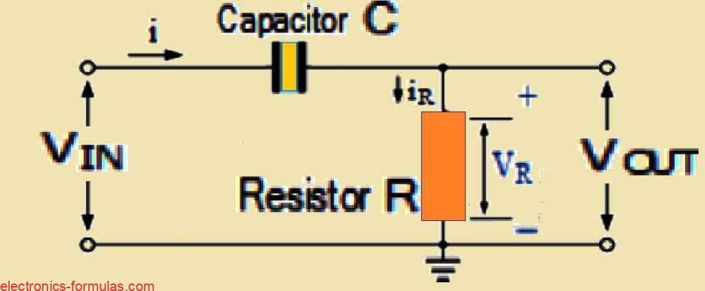
In an RC differentiator circuit, what happens is that you apply the input signal to one side of the capacitor and you take the output across the resistor.
Now this output which we call VOUT is actually the same as the voltage across the resistor or VR.
Here is the thing, since a capacitor is a frequency-dependent component, the charge that builds up across its plates is not something that happens immediately.
Instead it depends on the current and how it changes over time.
To be more specific, the amount of charge is actually equal to the integral of the current over time which means that the capacitor takes time to charge up.
It cannot just charge up instantly – it charges up in a gradual and exponential way.
If you remember from our tutorial on RC integrators, when we applied a single step voltage pulse to the input of an RC integrator, the output turned into a sawtooth waveform but that was only when the RC time constant was long enough.
Now the RC differentiator also modifies the input signal but it does it in a totally different way compared to the integrator.
So while both circuits change the input waveform they do so in their own unique manners.
Analyzing Voltage across the Resistor
So, like we mentioned before, in an RC differentiator circuit the output is the same as the voltage across the resistor which means VOUT is equal to VR.
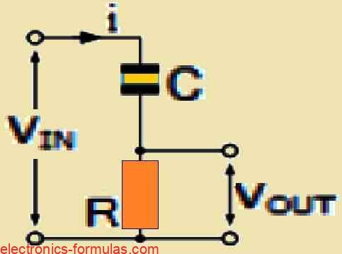
Since we are talking about a resistor here, the output voltage can change instantly. Resistors do not have any delay or anything when it comes to changes in voltage.
On the other hand, the voltage across the capacitor behaves very differently.
The capacitor cannot change its voltage instantly and that is because it is trying to store an electrical charge Q on its plates.
How fast the voltage changes across the capacitor depends on the value of its capacitance C.
Basically, the current flowing into the capacitor depends on how quickly the charge is changing across its plates.
So the current in a capacitor is not directly proportional to the voltage like it would be in a resistor but instead it is proportional to the rate at which the voltage is changing over time.
This is why the current through a capacitor is described by the equation i = dQ/dt which indicates that the current is equal to the rate of change of charge over time.
So the amount of charge that builds up across the plates of the capacitor is actually given by the equation:
Q = C * VC,
where C is the capacitance and VC is the voltage across the capacitor.
Basically the charge is just the capacitance times the voltage.
From this expression we can go ahead and derive the equation for the current flowing through the capacitor.
This might help us to understand how the current may be related to the charge and voltage across the capacitor.
Analyzing Current through Capacitor
The equation for the current flowing through the capacitor can be derived as shown below:
i(t) = dQ/dt = d(C * dVC)/dt = C(dVC/dt) = C(dVIN/dt)
So, VOUT is the same as VR, and according to Ohm’s law VR is equal to the current through the resistor iR multiplied by the resistance R.
That is basically the formula:
VR = iR * R.
Now, since the capacitor and the resistor are connected together in series, the current that flows through the capacitor has to also flow through the resistor.
There is no other path for the current to take.
So we can say that VOUT is equal to VR, which in turn is equal to R multiplied by iR.
In other words,
VOUT = VR = R * iR
∴ iC = C(dVIN/dt)
Since iR = iC,
∴ VOUT = RC(dVIN/dt)
So finally, we can write the standard equation for an RC differentiator circuit as shown below:
VOUT = RC(dVIN/dt)
So what we can see here is that the output voltage VOUT is actually the derivative of the input voltage, VIN.
This means that VOUT depends on how fast VIN is changing over time.
But there is also a constant involved, which is the constant RC.
RC represents the time constant which we call τ, for this series circuit. Essentially the time constant plays a role in “weighting” the relationship between the input and output voltages.
Effect of a Single Pulse input to an RC Differentiator
When we talk about a single pulse RC differentiator, what happens when you first apply a single step voltage pulse to the input is very interesting.
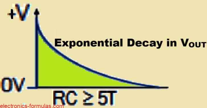
Initially the capacitor acts like a short circuit to the fast-changing signal.
This happens because the slope or the rate of change of voltage over time dv/dt, of the positive edge of a square wave is really large, ideally it would be infinite.
So, at the exact moment the signal shows up, all of the input voltage basically passes straight through to the output and appears across the resistor.
Once that sharp positive edge of the input signal is over and the peak value of the input becomes steady, the capacitor starts charging up in its usual way through the resistor.
This charging happens at a rate that is controlled by the RC time constant, which is τ = RC.
As the capacitor gradually charges up, the voltage across the resistor, and therefore the output voltage begins to drop in an exponential way.
This continues until the capacitor is fully charged which happens after a time period of 5 times the RC constant or 5T.
By the time the capacitor is fully charged, there will be no voltage across the resistor, meaning the output voltage drops to zero. At that point the voltage across the capacitor becomes equal to the input pulse, so we can say VC = VIN.
This will continue to be like this as long as the magnitude of the input pulse does not change.
Input Pulse Suddenly Changes and Drops Back to Zero
Now what happens if the input pulse suddenly changes and drops back to zero? The rate of change of the negative-going edge of the pulse, which is very fast, gets passed through the capacitor and shows up at the output.
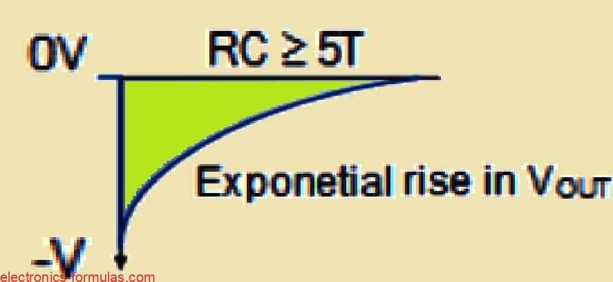
This is because the capacitor cannot react quickly enough to this rapid dv/dt change. What we get as a result is a negative-going spike at the output.
After this initial sharp drop in the input signal, the capacitor recovers and begins to discharge in its usual way.
As the capacitor discharges, the voltage across the resistor and therefore the output voltage starts to rise again but this time it increases in an exponential manner.
So whenever the input signal changes rapidly whether it is increasing or decreasing, we end up with a voltage spike at the output.
The polarity of this spike depends on the direction of the change in the input. If the input signal is going in a positive direction, we get a positive spike at the output.
On the other hand if the input signal is going in a negative direction, the output produces a negative spike.
So the output of the RC differentiator essentially becomes a graph that represents the rate of change of the input signal. It does not really look anything like the original square wave input anymore.
Instead, what you get are these narrow positive and negative spikes that show up whenever the input pulse changes its value.
Now if you start adjusting the time period T of the square wave input pulses while keeping the RC time constant fixed in the circuit, the shape of the output pulses will also change.
This means that by playing around with the timing of the input signal we can actually affect how the output pulses looks like, as shown in the following example.
Output Waveforms of an RC Differentiator Circuit
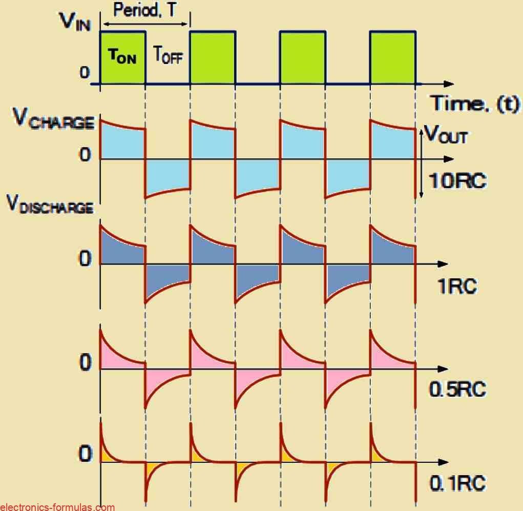
So what we can observe is that the shape of the output waveform is directly influenced by the ratio of the pulse width to the RC time constant.
When the RC time constant is much larger, let us say greater than 10RC, compared to the pulse width, then the output waveform starts to look like the square wave of the input signal.
On the other hand when the RC time constant is much smaller, less than 0.1RC, compared to the pulse width, the output takes on the form of these very sharp, narrow spikes, like the ones shown above.
By adjusting the time constant of the circuit, anywhere from 10RC to 0.1RC, we can generate a whole variety of different wave shapes.
Typically a smaller time constant is used in RC differentiator circuits because it helps produce nice, sharp pulses at the output across the resistor.
So when a square wave pulse (with a high dv/dt step input) goes through the circuit, its differential ends up being an extremely short spike. This is essentially what gives us the behavior of an RC differentiator circuit.
Analyzing a Practical RC Differentiator Circuit

Lets take an example where we have a square wave with a period T of 20 milliseconds.
This gives us a pulse width of 10 milliseconds which is just half of the period (20 milliseconds divided by 2).
Now for the spike to discharge down to 37% of its original value, the pulse width needs to match the RC time constant.
In other words the RC should be equal to 10 milliseconds.
If we decide to use a capacitor with a value of 1 microfarad (1 uF) we can then figure out the resistor value by using the formula for the RC time constant.
In this case, the R would come out to 10 kΩ.
Now if we want the output to look similar to the input square wave, we need the RC time constant to be ten times the value of the pulse width or 10RC.
For the same 1uF capacitor, this would mean the resistor should be 100 kΩ.
On the other hand if we are aiming for the output to look like a sharp pulse instead, we want RC to be one-tenth (0.1RC) of the pulse width.
Using the same 1 uF capacitor, this would give us a resistor value of 1 kΩ and so on.
So, simply by setting the RC value to be one-tenth of the pulse width (and in our example above, this would be 0.1 multiplied by 10 milliseconds, which equals 1 millisecond) or even lower, we can create the spikes at the output as desired by us.
The smaller the RC time constant is, relative to the pulse width, the sharper these spikes will be.
This means that if we lower the RC time constant for a given pulse width, then the spikes in the output become sharper and more defined.
Therefore the exact shape of the output waveform really depends on the value of the RC time constant that we choose.
Conclusions
In this article we have discussed RC circuits where the input signal is applied to one side of a capacitor, and the output is taken across a resistor.
This kind of circuit is specifically designed to generate spiked or trigger-type pulses which are really handy for timing applications.
When we feed a square wave step input into this RC circuit, the output waveform looks entirely different from the input.
The shape of the output depends on the periodic time T (and consequently the frequency f) of the square wave input, along with the RC time constant of the circuit.
If the periodic time of the input waveform is about the same as, or even shorter than (meaning the frequency is higher) the RC time constant of the circuit, then the output waveform ends up resembling the input which gives us more of a square wave shape.
But if the periodic time of the input waveform is significantly longer (or the frequency is lower) than the RC time constant, then the output changes and we start to see narrow positive and negative spikes.
These spikes happen because of the edges of the input square wave.
The positive spike in the output corresponds to the leading edge of the input square wave while the negative spike is caused by the falling edge.
So the output of an RC differentiator circuit really reflects how fast the input voltage changes, behaving a lot like the mathematical process of differentiation.
References:
RC differentiator circuit explaination
thank you so much
You are welcome!!