RC circuits have the ability to create various output shapes or waveforms, depending on the type and frequency (or period) of the signal applied to the input terminals.
It is similar to how the circuit “reacts” differently based on what is provided to it. In earlier lessons on RC Charging and Discharging we learned that a capacitor can both charge and discharge through a resistor connected in series with it.
When we apply or remove a constant DC voltage the time it takes for the capacitor to fully charge or fully discharge is always equal to five RC time constants, or 5T.
This is a fixed value tied to the combination of the resistor and the capacitor.
However let us change things a bit. What if instead of using that steady DC voltage we switch to a pulsed or square-wave signal?
This type of signal constantly flips between a maximum value and a minimum value at a rate that is determined by its frequency or time period.
How would this affect the shape of the RC waveform, especially when we still have the same RC time constant?
As we already know that, the capacitor charges up over a time of 5T when the voltage is applied, and it discharges back down over 5T when the voltage is removed.
This 5T time constant is a consistent value for RC charging and discharging circuits because it is directly based on the values of the resistor and capacitor.
Therefore if we ever want to change how long it takes for the capacitor to fully charge or discharge we cannot simply change the signal.
We would actually need to change the value of either the resistor or the capacitor in the circuit to make that happen. That is the only way to modify that timing.
Analyzing a Standard RC Waveforms Example

Square Wave Signal We can create the useful waveform shapes by using RC circuits that have the right time constant.
For example if we apply a continuous square wave voltage waveform to an RC circuit and the pulse width of that square wave matches exactly with the 5RC time constant (5T) of the circuit, we will see a specific behavior in the voltage across the capacitor.
The voltage waveform across the capacitor will create the RC waveforms that look something like this: So by choosing the right time constant we can control how the capacitor charges and discharges in response to the square wave.
The result is that the output waveform will have a unique shape based on how the square wave’s pulse width lines up with the circuits 5T value.
This interaction between the input signal and the time constant of the RC circuit gives us different waveforms at the output and in this case it will look like a certain type of RC waveform as shown below:
A Precision 5T RC Waveform Example
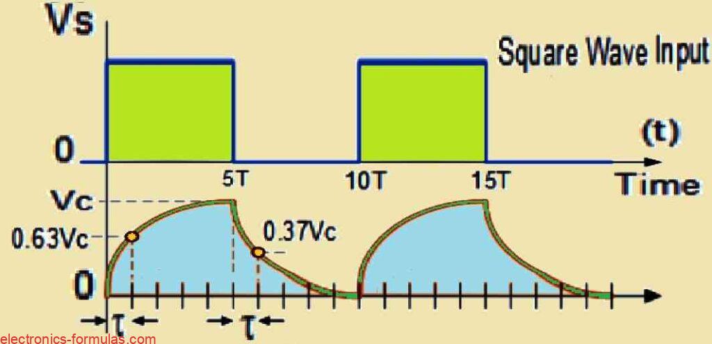
The voltage drop across the capacitor moves back and forth between charging up to Vc and discharging down to zero and this happens according to the input voltage waveform applied to the circuit.
In the example we are discussing the frequency of the input square wave voltage (and by extension, the time period, because frequency is calculated as f = 1/T) matches exactly twice the 5RC time constant.
So instead of just 5RC the overall time constant here is 10RC. This 10RC time constant is important because it gives the capacitor enough time to fully charge during the “ON” period of the input waveform which lasts from 0 to 5RC.
Then during the “OFF” period from 5RC to 10RC the capacitor has enough time to fully discharge. This creates an RC waveform where the charging and discharging phases are perfectly matched to the input waveform giving a smooth transition between the two.
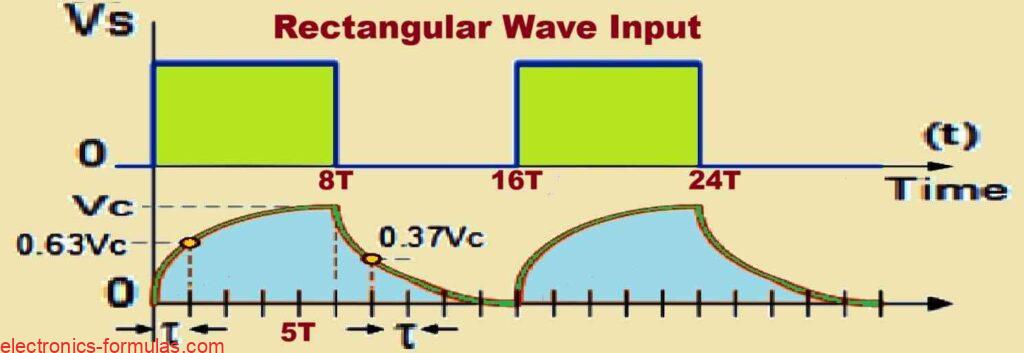
Now if we were to make the time period of the input waveform longer—which would mean lowering the frequency so that ƒ is less than 1/10RC, for example if the “ON” pulse width stretched to something like 8RC—the capacitors behavior would change a little.
With this longer time period the capacitor would continue to be fully charged for a longer time during the “ON” phase and would also stay fully discharged for a longer time during the “OFF” phase.
This would produce a different RC waveform where the capacitor holds its charged and discharged states for an extended period as shown in the following illustration.
An 8RC Input Illustrating Longer Waveforms
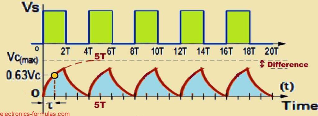
Now if we reduce the total time period of the input waveform which means increasing the frequency so that the “f” is greater than 1/10RC—let us say to a value like 4RC—the behavior of the capacitor changes.
In this case the capacitor would not have enough time to fully charge during the “ON” period or to fully discharge during the “OFF” period.
Because the time is shortened the voltage drop across the capacitor VC, would be less than the maximum input voltage.
This means that the capacitor does not have the chance to reach its full charging potential or to completely discharge, resulting in a waveform that looks different from when it has more time.
The RC waveform in this situation would show a lower overall voltage swing as shown in the following diagram.
A Frequency of 4T Exhibiting Shorter RC Waveform
By adjusting either the RC time constant or the frequency of the input waveform we can control the voltage across the capacitor creating a relationship between the capacitor voltage Vc, and time t.
This relationship can be manipulated to alter the shape of various waveforms. In fact by making the right adjustments, the output waveform across the capacitor may look very different from the original input waveform.
Frequency Response of an RC Integrator Circuit
An RC Integrator is a type of Low Pass Filter circuit. What it does is convert a square wave input signal into a triangular waveform as the output.
As mentioned earlier if the 5RC time constant is much longer than the time period of the input RC waveform, the output waveform will take on a triangular shape.
Also as the input frequency increases, the output amplitude becomes lower when compared to the input signal.
So this circuit not only reshapes the waveform but also reduces the amplitude of the output as the input frequency rises.
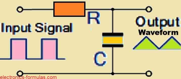
Using the above date allows us to derive an ideal voltage output from an integrator circuit as shown below:
VOUT = 1/RC∫0t Vin dt
Analyzing an RC Differentiator Circuit
The Differentiator is a type of High Pass Filter circuit that can take a square wave input signal and convert it into sharp high-frequency spikes at its output.
If the 5RC time constant is shorter than the time period of the input waveform then the capacitor charges up much more quickly, and gets fully charged before the next change in the input signal can happen.
When the capacitor becomes fully charged then the output voltage across the resistor drops to zero.
But as soon as the input waveform hits a falling edge then the capacitor reverses its charge resulting in a negative spike in the output.
So with each change in the square wave input, the output produces spikes that alternates between positive and negative values, following the pattern of the input waveform.
This back-and-forth switching is what creates the distinct spikes in the output signal.
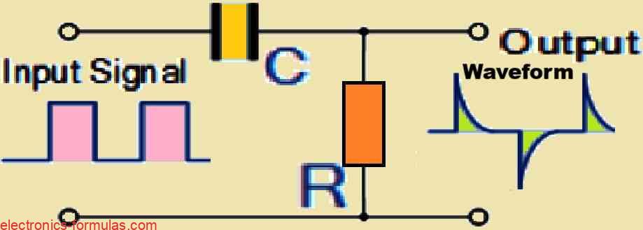
Using the above data we can derive the equation to get an ideal voltage output from an Differentiator circuit, as given below:
VOUT = RC(dVin/dt)
Impact of an Alternating Sine Wave at the input of RC Circuits
Now if we switch the input waveform for the above discussed RC circuits from a square wave to a sinusoidal sine wave voltage signal then the general shape of the output waveform will remain the same.
However its amplitude will change depending on the characteristics of the circuit.
By altering the position of either the Resistor R, or the Capacitor C, we can create a simple first-order Low Pass or High Pass filter.
The frequency response of these two circuits depends directly on the input frequency.
For Low Pass filters, the lower-frequency signals will pass through from the input to the output with little to no attenuation; meaning their strength stays nearly the same.
On the other hand, the higher-frequency signals are attenuated or weakened significantly and potentially being reduced to almost zero.
The reverse happens with a High Pass filter where high-frequency signals pass through easily while lower frequencies are attenuated.
The point where the response drops by 3dB is known as the cut-off frequency fC, and is used to define the filter’s bandwidth.
A 3dB loss becomes equivalent to a decrease in the output voltage to about 70.7 percent of its original value, which marks the boundary at which the filter starts to significantly impact the signal.
The details can be understood by looking at the following formula:
fc = 1 / 2πRC (Hertz)
In the above formula, the RC represents the time constant of the circuit, something we have already discussed before and it can also be symbolized by the Greek letter tau τ.
This is just another way to express the same concept. What this shows us is that how the ideas of the Time Domain and the Frequency Domain are connected to one another.
It is a good example of how changes in time can influence frequency and vice versa, demonstrating the relationship between these two important concepts in circuit theory.
References:
Triangular wave response of RC circuit
RC circuit waveforms not lining up on oscilloscope (capacitor starting negative)
Leave a Reply