We know that the Butterworth filter is a useful tool for electronics professionals but there is a trade-off with its performance. It is superior to other filter types in that it produces a completely flat response in the passband and stopband, but this ideal characteristic comes at the price of a wider transition band. This transition […]
Understanding Second Order Filter Circuits with Formulas
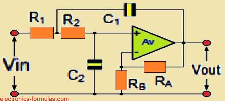
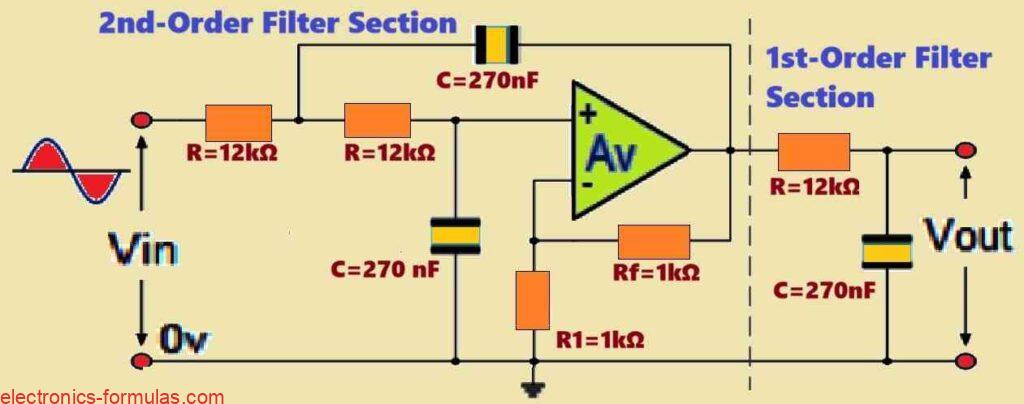
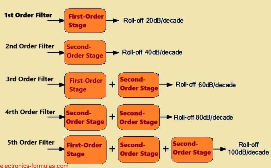
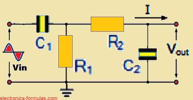
Second-order filters, often known as VCVS filters since their operational amplifier works like a Voltage Controlled Voltage Source amplifier, are a critical category in active filter design. These serve as fundamental elements for the construction of higher-order filter circuits, extending on previously researched active first-order RC filters. Our analysis of analog filters has included both passive […]
Understanding Active Band Pass Filter Circuits with Formulas
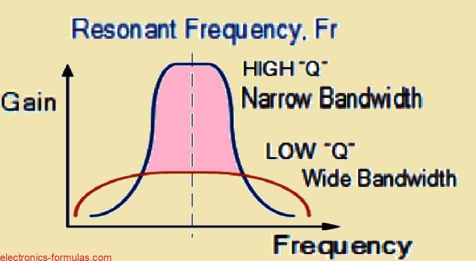
Before we begin our tutorial on active band pass filter circuits, let’s first look at the passband characteristics of several filter types. Low-Pass Filters (LPFs): An LPF’s passband begins at 0 Hz (DC) and extends to the set cut-off frequency (fC). This cut-off frequency corresponds to -3 dB with respect to the maximum passband gain. […]
Active High Pass Filter Circuits Explained with Calculations
Although the fundamental filtering mechanism continues to be the same as in the passive RC filter, the active high-pass filter (HPF) integrates an operational amplifier (op-amp) to provide some essential characteristics. Gain & Control: The op-amp amplifies and controls the gain response of the filter. This is a huge benefit over passive high-pass filters, which […]
Understanding Active Low Pass Filter Circuit with Calculations
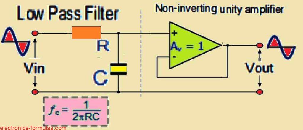
As we learned in our previous tutorial, passive filter circuits depend exclusively on passive components such as resistors (R) and capacitors (C) to provide filtering characteristics. A simple example is a first-order low pass filter built with a series resistor and a shunt capacitor across a sinusoidal input. Active filters on the other hand use […]
Understanding Passive Band Pass Filter with Formulas
The purpose of passive band pass filters is to filter or isolate particular frequencies within a given band. As a result, undesired frequencies outside of the intended range can be attenuated while the right frequencies can flow through selectively. As was previously noted, a non-polarized capacitor and a single series resistor may be used to accurately […]