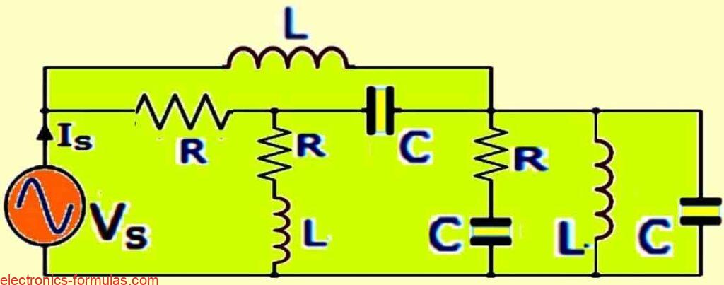
Passive components control or limit electrical signals, but can’t amplify them. Meaning, they can affect the signal in various ways, but not boost its power. In an electrical circuit we connect various parts to create a closed loop where electricity can flow. Three key parts that are involved are resistors, capacitors, and inductors. These are all […]
Calculating Harmonics in AC Circuits

Lets imagine a smooth alternating wave, harmonics are like ripples on top of that wave, making it look messy and uneven. These ripples are higher pitched sounds that mess with the original sound. Forget perfect sine waves….. In real circuits, many devices don’t play by the ideal rules. These are called non-linear devices. Because they’ […]
Calculating Reactive Power in AC Circuits

Reactive power (Q) is the oscillating energy exchange in AC circuits due to inductors and capacitors, which does not contribute to real power (P). When the circuit is a DC circuit, we can quickly multiply volts by amps to get watts of power used. This is true to purely resistive AC circuits as well. But […]
Calculating Average Voltage of Sinusoidal Waveform

Finding the average voltage of an alternating waveform is similar to finding its RMS value, but without squaring the instantaneous values or taking the square root of the final average. The average voltage (or current) of any waveform for example like a sine wave, square wave, or triangular wave, is like a DC value for […]
Calculating Root Mean Square (RMS) Voltage

In the preceding AC Waveform analysis we introduced the concept of RMS (Root-Mean- Square) voltage applicable to sinusoidal waveforms. We learned that, the RMS voltage of a sine wave corresponds to the DC voltage level that would produce identical heating in a resistive element. This tutorial expands upon this foundation, by investigating into a more […]
Calculating Parallel RLC Resonance Circuit

Like series circuits, parallel RLC circuits (containing inductors and capacitors) are second-order with a resonant frequency. Both are affected by frequency changes. However in parallel resonance, it is the current through the circuit that reaches a minimum at resonance, not the impedance. The focus here is, how currents in each branch of the parallel LC […]