An asynchronous counter is really cool because it can handle a total of 2n-1 different counting states. For example a 4-bit counter set up as MOD-16 can count from 0 all the way to 15, making it great for things like frequency division. But you can also use the basic design of an asynchronous counter […]
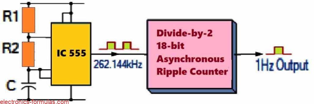
Understanding Frequency Division: “Divide-by-2” Counter

In our previous lessons about Sequential Logic we learned how D-type Flip-Flops work and how we can connect them to make a Data Latch. One cool thing about D-type Flip-Flops is that they can act as a binary divider which is great for dividing frequencies or working as a “divide-by-2” counter. In this setup, the […]
Understanding Audio Transformer with Calculations
Transformers are really cool devices, that do more than just change the voltage of signals. One of their awesome features is called isolation. This means that there is no direct electrical link between the primary and secondary coils, which keeps the input and output circuits completely separate. This isolation is super useful in audio transformers […]
Transformer Voltage Regulation: Explained with Formulas
When we talk about voltage regulation we are looking at how good a transformer is at keeping its secondary voltage steady even when the load changes. Sometimes the output voltage we get from the secondary side is not exactly what we were expecting and that is where voltage regulation comes into play. Now when you […]
Explained: Three Phase Transformers and Calculations
A 3-Phase electricity is basically a method we use to create and send electric power over really long distances so that our offices and industries can use it. In this setup we deal with three-phase voltages and currents which we can adjust either increase or decrease, using three-phase transformers. These transformers are pretty cool because […]
Current Transformer Explained with Calculations
We use a Current Transformer (C.T.) as an “instrument transformer.” It creates an alternating current in its secondary winding that matches the current in its primary winding. Current transformers lower high voltage currents to safer levels. They help us monitor the actual electrical current in an AC transmission line using a standard ammeter. The way […]