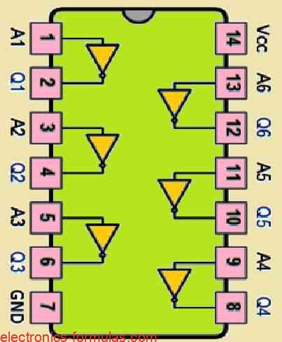
A NOT gate which is also known as an inverter, is a digital logic component with a single input and a single output. The basic function of a NOT gate is to invert the input signal to generate an exactly opposite signal at its output. For example, suppose if we apply input of a NOT […]
How the OR Gate Works: A Tutorial
In digital logic circuits, a “Logic OR Gate” functions depending on the specific conditions we apply to its input to produce its output which is written as Q. We get a LOW output from an OR gate only when all of its inputs are applied with a LOW state (logic level “0”), and if any […]
Understanding the Logic AND Gate: A Comprehensive Guide
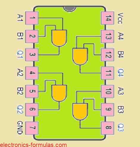
A digital logic AND gate is a type of circuit that produces an output based on its two inputs. For an AND gate you will find that its output is only “HIGH” (which means true or 1) whenever both of its inputs are “HIGH” (true or 1). If we turn either of inputs “LOW” (false […]
Understanding Digital Logic Gates: From Basic Functions to Advanced IC Classifications
Normally you will find a digital logic gate will accept multiple inputs, for example A, B, C, D, etc., but would mostly provide only one digital output, denoted as Q. We can connect or cascade multiple individual logic gates, to generate logic gate functions with any desired number of inputs, which can be used to […]