A capacitor is a device that can store electric charge on its conductive plates. The amount of charge (Q) that a capacitor can store depends on the voltage difference between its plates.
When a capacitor is connected to an alternating current (AC) circuit, its capacitance affects how well it can store and release charge as the voltage changes.
DC Charging and Discharging
When connected to a direct current (DC) supply, a capacitor charges to the supply voltage and retains the charge while connected.
The charge current (i) is described by i = C(dv/dt), where C is capacitance and dv/dt is the voltage change rate. Once fully charged, the capacitor blocks further electron flow.
AC Capacitance Behavior
Even without a DC voltage, a capacitor can store charge. When connected to an AC source, it exhibits periodic charging and discharging based on the source frequency.
In the case of a sinusoidal AC voltage, the capacitor undergoes polarity changes in sync with the voltage’s positive and negative cycles.
Let’s understand this through the following diagram:
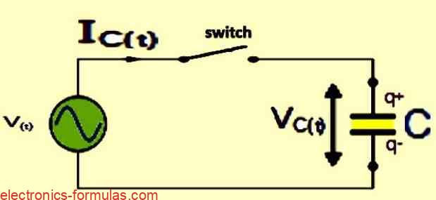
Circuit Initialization (t = 0)
At t = 0, the switch in the circuit is closed, and the capacitor is devoid of charge.
Simultaneously, the sinusoidal supply voltage (V) is positive, reaching its maximum rate of increase as it passes through the zero reference axis at an angle of 0o.
Peak Charging Phase (0o to 90o)
During this phase, the potential difference across the plates undergoes its maximum rate of change, causing the capacitor current to peak.
This results in the transfer of the maximum number of electrons between the capacitor plates.
Momentary Pause (90o)
As the sinusoidal supply voltage reaches its peak at 90o, it decelerates, causing a momentary pause in the potential difference across the plates.
The current drops to zero during this interval due to the absence of voltage change.
Capacitor Fully Charged (90o)
At the 90o point, when the potential difference across the capacitor plates reaches its maximum value (Vmax), the capacitor ceases to charge. It is fully charged, and no further current flows into it.
Discharge Phase (90o to 180o)
As the supply voltage falls from its peak towards the zero reference line at 180o, the capacitor releases stored electrons to maintain a constant voltage.
This results in a reversal of capacitor current direction, flowing negatively.
Maximum Negative Slope (180o)
At instant 180o, the sinusoidal supply voltage waveform crosses the zero reference axis with the maximum negative slope.
Consequently, the capacitor current reaches its maximum rate, and the potential difference across the plates becomes zero.
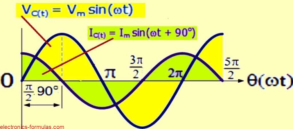
Phase Relationship (0o to 180o)
When the current in a circuit with a pure capacitor goes from 0o to 180o, it reaches its peak positive value sooner (1/4ƒ) than the voltage.
Therefore, the voltage is delayed by a quarter of a cycle or 90o compared to the current.
Voltage Reversal and Capacitor Discharge
Supply Voltage Transition (180o to 270o)
As the supply voltage changes direction from 180o to 270o, it reaches its lowest point at 270o.
Capacitor Fully Charged (270o)
When the plates reach their maximum negative potential, the potential difference between them becomes constant, and no more current flows.
The capacitor is fully charged and its state is like the one at 90 degrees, but reversed.
Discharge and Renewal
Negative to Positive Transition (270o to 360o)
When the supply voltage changes from negative to positive at 360o, the capacitor that is fully charged releases extra electrons to keep a steady voltage.
It discharges until the supply voltage reaches zero at 360o, and then the cycle of charging and discharging repeats.
Phase Relationship Analysis
Current-Leading Phenomenon
The current waveform is always ahead of the voltage waveform by a quarter of a cycle or 90o, which is equal to π/2. This happens because of the process of charging and discharging the capacitor.
Capacitance vs. Inductance Phase Relationship
As we saw in a previous tutorial, the phase relationship between voltage and current in an AC capacitance circuit is opposite to that in an AC inductance circuit.
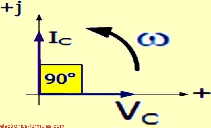
Phasor Representation
Lagging Voltage, Leading Current
A phasor diagram can clearly show this effect, by proving that the voltage is 90o behind the current in a purely capacitive circuit.
Or, if we use the voltage as a reference, we can say that the current is 90o ahead of the voltage by one quarter of a cycle, as indicated in the following vector diagram.
Phase Relationship in Pure Capacitor
Lagging Voltage, Leading Current
A pure capacitor has a 90o phase difference between the voltage across it, VC, and the current flowing through it, IC.
This means that the current is 90o ahead of the voltage, or the voltage is 90o behind the current.
Mnemonic Expression: “ICE”
Simple Memory Aid
A mnemonic expression to remember the phase relationship in a pure AC capacitance circuit is “ICE”.
It means that the current (I) leads the capacitance (C) and the electromotive force (E) in a capacitor circuit. I, C, E spells “ICE”. This expression is valid for any initial phase angle of the voltage in a pure AC capacitance circuit.
Understanding Capacitive Reactance
Capacitor’s Response to Voltage Changes
Capacitors resist voltage changes by controlling how many electrons enter or leave their plates. The faster the voltage across the capacitor changes, the more electrons flow in or out during charge or discharge.
Distinction from Resistors: Reactance
Capacitors have a different way of opposing current flow than resistors, which use resistance. The opposition in capacitors is called Capacitive Reactance, or (XC), and it is measured in Ohms.
Measurement and Symbolism
Reactance, like resistance, has the unit of Ohms. But it uses the symbol X instead of R to show that it is not purely resistive. For capacitors, the reactance is called Capacitive Reactance and written as XC.
Proportional Charging and Discharging
Capacitors charge and discharge faster when the voltage across them changes faster. This means that more current flows when the voltage changes more rapidly. On the other hand, less current flows when the voltage changes slower.
This shows that the reactance of a capacitor in an AC circuit is “inversely proportional” to the frequency of the power source, as shown below.
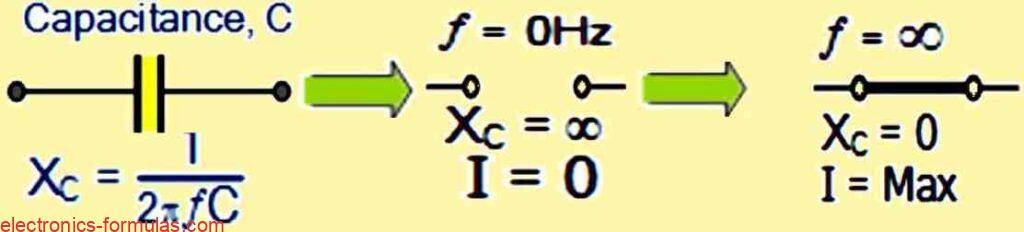
XC = 1 / 2πfC
Where: XC denotes the Capacitive Reactance in Ohms, ƒ is the symbol for the frequency in Hertz and C gives us the AC capacitance in Farads, represented by F.
A similar concept to capacitive reactance in AC circuits is the angular frequency in radians, denoted by omega, ω, which is equal to 2π times the frequency, ƒ.
XC = 1 / ωC
The formula shows a key relationship: as the frequency increases, the capacitive reactance and the total impedance in Ohms decrease towards zero. This means it acts like a short circuit.
High-Frequency Behavior
Capacitors become more conductive as the frequency increases, because their capacitive reactance acts like a short circuit at higher frequencies. This is a characteristic of capacitors.
Low-Frequency Behavior
A capacitor’s reactance increases as the frequency of the current decreases and approaches zero or direct current (DC). This means that capacitors act as open circuits and block DC, since their reactance is very high or infinite in this case.
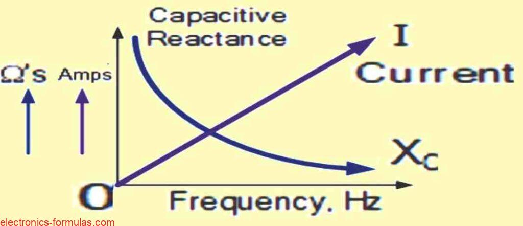
Inverse Relationship with Frequency
Comparing with Inductive Reactance
A previous tutorial explained that inductive reactance (XL) has a direct relationship with frequency. Capacitive reactance, on the other hand, has the opposite relationship. It is “inversely proportional to frequency.”
Frequency Impact
Capacitive reactance is inversely proportional to frequency. As the frequency gets lower, the capacitive reactance gets higher.
As the frequency gets higher, the capacitive reactance gets lower. This is how capacitors behave in AC circuits.
Capacitive Reactance and Frequency Relationship:
Capacitive reactance is the measure of how a capacitor resists the flow of alternating current. It depends on the frequency of the current across the capacitor’s plates.
The higher the frequency, the lower the capacitive reactance. The lower the frequency, the higher the capacitive reactance.
Inverse Proportionality and Current Opposition:
Current flow is resisted by capacitive reactance.
The electrostatic charge on the plates (AC capacitance value) does not change.
Absorption of Charge during Frequency Changes:
As the capacitive reactance decreases, the capacitor can more easily adjust to the charge variations in each half cycle.
The plates of the capacitor maintain a steady electrostatic charge throughout this process.
Impact of Frequency on Current Flow:
The current flowing into the capacitor increases with the frequency. This happens because the voltage across the capacitor plates changes faster.
Effect of Frequency on Reactance in Pure AC Capacitance:
The reactance of a pure AC capacitance depends on the frequency of the AC current. At very low or very high frequencies, the capacitor’s reactance changes significantly.
Here are the effects of these extreme frequencies on the reactance of the capacitor.
In an AC circuit current flowing into the pure capacitor can be expressed as:
IC(t) = dq / dt where: q = CVC = CVmax sin(ωt)
∴ IC(t) = (d / dt)CVmax sin(ωt) = ωCVmaxcos(ωt)
If: Imax = Vmax / XC where: XC = 1 / 2πfC = 1 / ωC
then: Imax = ωCVmax
Hence, the following equation describes the root mean square (rms) AC current in a capacitor:
IC(t) = Imax sin(ωt + 90o)
In the given equation, IC = V/(1/ωC) (or IC = V/XC), IC represents the magnitude of the current, and θ = +90o denotes the phase difference or angle between the voltage and current. In the case of a purely capacitive circuit, Ic leads Vc by 90o, or alternatively, Vc lags Ic by 90o.
Phasor Domain
When using phasors to represent AC voltages, the voltage across a capacitor’s plates can be expressed as:
VC = (1 / jωC) x IC
where: 1 / jωC = jXC = 1 / 2πfC = Impedance, Z
In polar form, we can express this as: XC∠-90o, where:
XC∠θ = (VC∠0o) / (VC∠+90o)
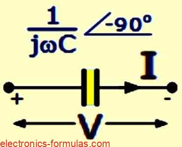
XC∠θ = 1 / jωC = 0 – jXC = (1 / ωC)∠-90o = Z∠-90o
Introduction to AC Across a Series R + C Circuit:
When we study how current behaves in a capacitor that only has AC voltage, we find that the current is 90o ahead of the voltage in phase.
But in reality, capacitors always have some internal resistance, which causes some current to leak.
Impurities in Capacitors:
A real capacitor has some internal resistance, which makes it an “impure capacitor.”
This means that there is a series resistance, R, along with the capacitance, C, in the circuit.
Total Impedance Representation:
The total impedance of the capacitor in an AC circuit with both capacitance and resistance is the series combination of resistance (R) and capacitance (C), which accounts for internal resistance.
The voltage phasor (V) across this combination is the phasor sum of the component voltages (VR and VC).
Voltage Phasor Sum:
The capacitor’s current still leads the voltage, but the lead is less than 90 degrees now.
The phase angle Φ determines the degree of phase lead, which depends on the values of R and C. The phasor sum reflects this angle.
Series RC Circuit Illustration:
In this series RC circuit, an ohmic resistor (R) and a pure capacitor (C) are connected in series. The following circuit shows how resistance and capacitance affect the alternating current flow.
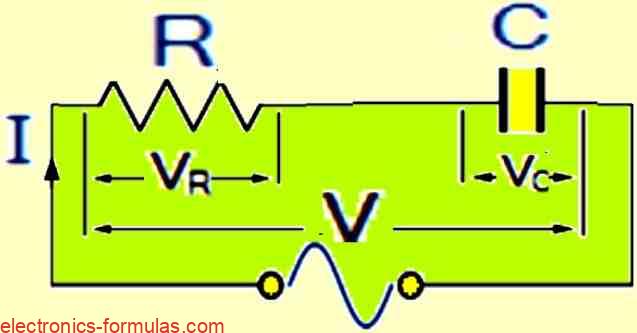
Current Distribution in the RC Series Circuit:
A common current flows through both the resistance and the capacitance in the RC series circuit. The voltage, however, has two separate components: VR and VC.
Mathematical Analysis of Component Voltages:
To find the voltage that results from the combination of resistance and capacitance, we can use mathematical analysis.
Because vectors VR and VC have a 90o phase difference, we cannot add them directly. Instead, we need to use a vectorial addition, which involves drawing a vector diagram.
Vectorial Addition of VR and VC:
The mathematical approach is valid, but the vectors VR and VC are out of phase, so they need to be added vectorially.
A vector diagram is a useful way to show the result of adding these two components.
Establishing a Reference Component:
A common or reference component is needed to draw a vector diagram for an AC capacitance.
In a series AC circuit, the same current flows through both resistance and capacitance, and it serves as the reference source.
Individual Vector Diagrams for Resistance and Capacitance:
Here we see the vector diagrams for a pure resistance and a pure capacitance. Each diagram highlights the specific features of each component.
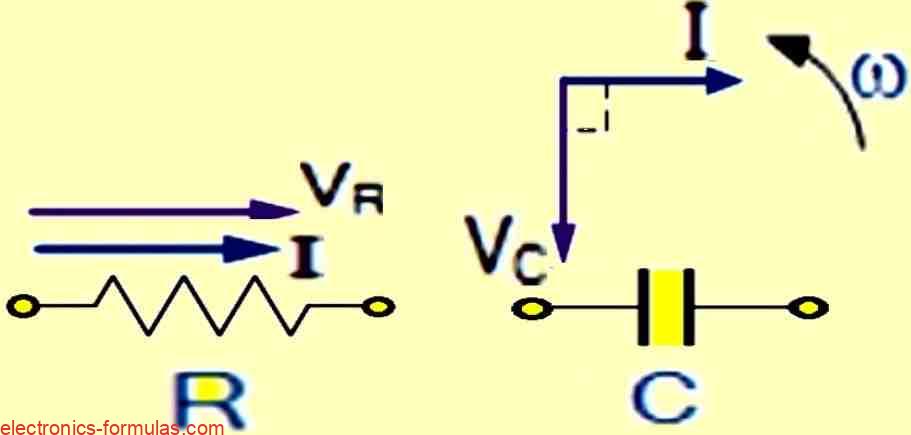
These diagrams are essential for building the complete vector diagram in the series RC circuit.
For an AC Resistance, the voltage and current vectors have the same phase, so the voltage vector VR is drawn on top of the current vector with the same scale.
A pure AC capacitance circuit has the current leading the voltage (ICE). Thus, we draw the voltage vector VC 90o behind (lagging) the current vector, using the same scale as VR.
Diagram illustrating the Combined or Resultant Voltage Vectors.
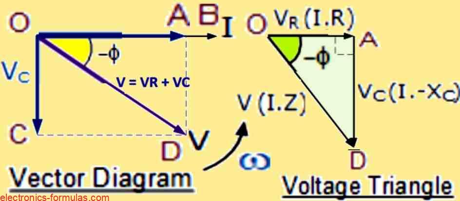
The vector diagram shows the main elements, where the line OB is the horizontal reference for the current.
Resistive Component Voltage (OA):
The resistive component has the same phase for its voltage and current, represented by line OA.
This section explains how the current and voltage in the resistive element are related.
Capacitive Voltage Representation (OC):
The capacitive voltage is shown by line OC, which is 90o lagging behind the current.
It is clear that the current is 90o ahead of the purely capacitive voltage, despite the phase difference.
Resultant Supply Voltage (OD):
The vector diagram is complete with the segment OD, which shows the total supply voltage that accounts for both the resistance and capacitance in the series RC circuit.
Phasor Diagram for Pure Capacitance:
The phasor diagram shows the individual voltage drops VR and VC, which form a right-angled voltage triangle (OAD).
This diagram illustrates how the current in a pure capacitance leads the voltage by 90 degrees.
Application of Pythagoras Theorem:
To find the total voltage across the resistor/capacitor (RC) circuit in series, we can use the Pythagorean theorem. This method gives us a numerical measure of the combined voltage in the RC circuit.
Since the voltage across the resistor (VR) is equal to the product of the current (I) and the resistance (R), and the voltage across the capacitor (VC) is equal to the product of the current (I) and the capacitive reactance (XC), the total voltage applied to the circuit (V) will be the vector sum of VR and VC, as shown below.
V2 = V2R + V2C
VR = I x R and VC = I x XC
V2 = I2 x R2 + I2 x X2C
V = √(I x R)2 + (I x XC)2
The impedance, Z of the circuit is given by the expression √R2 + X2c, where R is the resistance and Xc is the capacitive reactance.
AC Capacitance Impedance:
The impedance (Z), is the total opposition to the flow of alternating current (AC) in a circuit. Impedance is measured in ohms (Ω), the same unit as resistance, but it also takes into account the effects of capacitance and inductance.
Components of Impedance:
Impedance is the term that describes the “TOTAL” opposition to an alternating current, which consists of two components: Resistance (the real part) and Reactance (the imaginary part).
The units of impedance are Ohms, which are denoted by the symbol Ω.
Purely Resistive and Capacitive Impedances:
To find the phase angles of purely resistive and capacitive impedances, we can use these rules:
- A purely resistive impedance has a phase angle of 0 degrees.
- A purely capacitive impedance has a phase angle of -90 degrees.
Composite Impedance in Mixed Circuits:
We see that the circuit contains both resistors and capacitors, which create a combined impedance that has a phase angle between 0 and 90 degrees.
The exact value of the phase angle varies according to the particular values of the components.
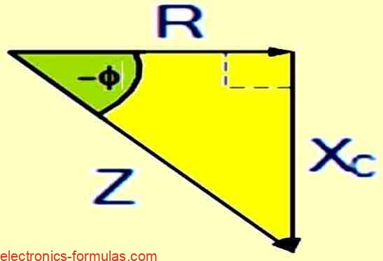
Impedance Determination in RC Circuits:
Now let’s see how to find the impedance of a simple RC circuit, which consists of resistors and capacitors.
The following diagram shows how to use the impedance triangle, a diagram that helps to calculate the total impedance in the circuit.
Impedance, Z = V / I
Z = √R2 + X2C
∴ Z2 = R2 + X2C
Now: Impedance2 = Resistance2 + (j x Reactance)2
Here, j is the imaginary unit that indicates a 90-degree phase shift.
So, we can apply Pythagoras theorem to find the negative phase angle, θ, that shows how much the current lags behind the voltage.
Z2 = R2 + X2C
cosΦ = R / Z, sinΦ = XC / Z, tanΦ = XC / R
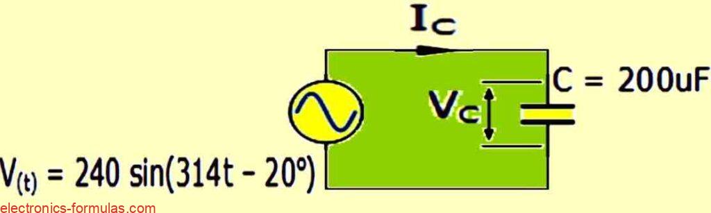
Solving an AC Capacitance Problem
A pure AC capacitor of 200uF is connected to a single-phase sinusoidal AC supply voltage, which is given by the expression: V(t) = 240 sin(314t – 20°).
The current flowing into the capacitor and the corresponding phasor diagram are to be determined.
A possible way to rewrite the text is:
We can assume that the supply voltage and the peak voltage across the capacitor are equal. If we express this value in polar form, we get: VC = 240 ∠-20o (v). The capacitive reactance is given by:
XC = 1/( ω.200µF)
Using Ohms law, we can calculate the maximum instantaneous current that flows into the capacitor as:
Xc = 1 / jωC = 1 / (314 x 200µF) = 16∠-90o
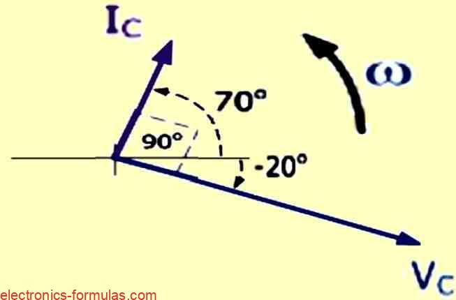
IC(t) = VC / jXC = (240∠-20o) / (16∠-90o) = 15∠70o (Am)
Since in an AC capacitance circuit, the current is 90o ahead of the voltage. The phasor diagram for this circuit will look like this.
Another Example of Solving AC Capacitance
A capacitor has a capacitance of 100uF and an internal resistance of 10Ω. It is connected to a supply voltage of the form V(t) = 100 sin (314t).
Find the maximum instantaneous current that flows into the capacitor. In addition, draw a voltage triangle that illustrates the separate voltage drops.
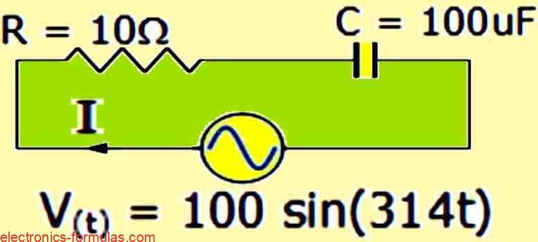
We can find the capacitive reactance and the circuit impedance by using these formulas:
Xc = 1 / ωC = 1 / (314 x 100μF) = 31.85Ω
The peak current that flows through the circuit and charges the capacitor can be expressed as:
I = Vc / Z = 100 / 33.4 = 3 Amps
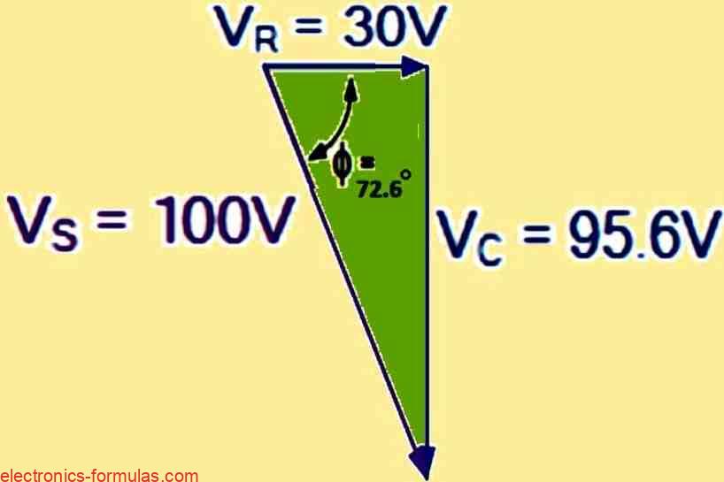
We can use the impedance triangle above to find the phase angle between the current and voltage. The formula is:
Φ = tan-1(Xc / R) = 31.85 / 10 = 72.6o leading
To calculate the individual voltage drops around the circuit, we use the following formula:
VR = I x R = 3 x 10 = 30V
VC = I x Xc = 3 x 31.85 = 95.6V
Vs = √VR2 + VC2 = √302 + 95.62 = 100V
We can use the calculated peak values to draw a voltage triangle as follows:
Conclusion
A pure AC capacitance circuit has a 90° phase difference between the voltage and the current, where the current is ahead of the voltage. You can use the acronym “ICE” to recall this fact.
A capacitor’s AC resistance, called impedance (Z), depends on the frequency of the current through capacitive reactance (XC). For an AC capacitance circuit, XC is equal to 1/(2πƒC) or 1/(jωC), where ƒ is the frequency and C is the capacitance.
Pure passive components have different relationships between voltage and current. The phase angle is 0° for resistance, +90° for inductance, and -90° for capacitance.
Leave a Reply