In AC circuits, the relationship between different types of power (real and reactive and apparent) can be depicted by a right triangle known as the power triangle.
Power Triangles in AC Circuits with Impedance
Our previous lesson covered real and reactive power in AC circuits containing resistance and either capacitance or inductance (or both).
To calculate and draw a power triangle for the total power consumed, we need to know the phase difference between the voltage and current waveforms.
Sine Waves and In-Phase Power:
In AC circuits, voltage and current are sine waves, meaning their strength constantly changes over time.
We know, power equals voltage times current (P = VI).
Maximum power occurs when the voltage and current peaks and zero points perfectly align in time. This alignment is called “in phase.”
Impedance and Phase Shift:
Three main components in an AC circuit impact the voltage, current relationship and their phase difference: resistors, capacitors, and inductors.
These component determine the circuit’s total impedance (Z) which is similar to resistance in DC circuits but measured in ohms. However, in AC circuits, impedance is the ratio of voltage and current phasors created by a circuit element.
Phasors and Impedance Triangles:
Phasors are lines, representing voltage or current amplitude by their length and phase difference with other phasors by their angle relative to them. AC circuits combine resistance and reactance to create a total impedance (Z) that limits current flow.
Importantly, unlike DC circuits, impedance is not a simple sum of resistance and reactance because pure resistance and pure reactance cause a 90° phase shift.
However we can leverage this 90° phase shift, to create a right angled triangle called an impedance triangle.
Impedance acts as the hypotenuse of this triangle, calculated using the Pythagorean theorem. This geometric relationship between resistance and reactance, and impedance is visually represented by the impedance triangle as indicated below:
Impedance Triangle and Power Triangle Relationship
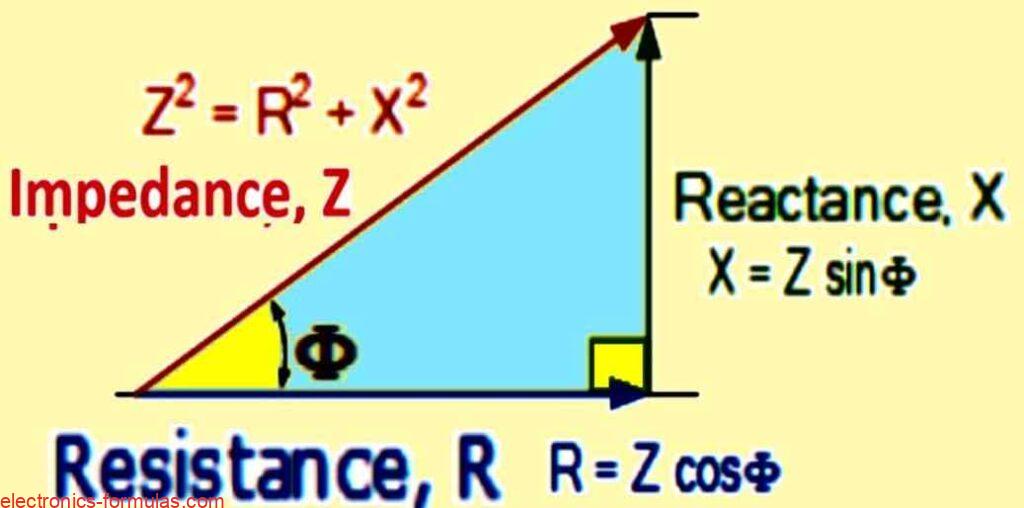
- Z2 = R2 + jX2 (Ω)
- cosΦ = R / Z
- sineΦ = X / Z
- tanΦ = X / R
Remember that impedance (Z) is the combined effect of resistance (R) and reactance (X), acting like a vector sum.
It has both a magnitude (absolute value) and a phase angle (Φ) reflecting the phase difference between resistance and reactance.
This triangle’s shape changes based on variations in reactance (X) with frequency, while resistance (R) stays constant.
We can further analyze this concept by transforming the impedance triangle into a power triangle, representing the three key power elements in AC circuits.
Ohms Law defines power (P) in DC circuits as current squared (I²) multiplied by resistance (R).
Applying this logic, we can multiply each side of the impedance triangle by I² to get the corresponding sides of the power triangle:
- Real Power (P) = I²R (Watts, W): This represents the actual power used for work in the circuit.
- Reactive Power (Q) = I²X (Volt-amperes Reactive, VAR): This represents the power exchanged between the circuit and reactive components (capacitors and inductors) but not used for work.
- Apparent Power (S) = I²Z (Volt-amperes, VA): This represents the total power delivered by the source, which can be further divided into real and reactive power.
Understanding Real Power in AC Circuits
Real Power (P): The Workhorse
Real power (P) which is also called true or active power, is the workhorse of an electrical circuit. Measured in watts (W), it represents the power dissipated by the resistive elements.
Unlike reactive power, real power gets used to perform actual work in the circuit, such as heating elements, powering motors, or generating light.
Calculating Real Power in AC and DC Circuits
The good news is that, calculating real power in AC circuits is similar to DC circuits. They both use the formula P = I² * R, where:
- P is real power (W)
- I is the current (A) (rms value in AC circuits)
- R is the total resistance (Ω) of the circuit
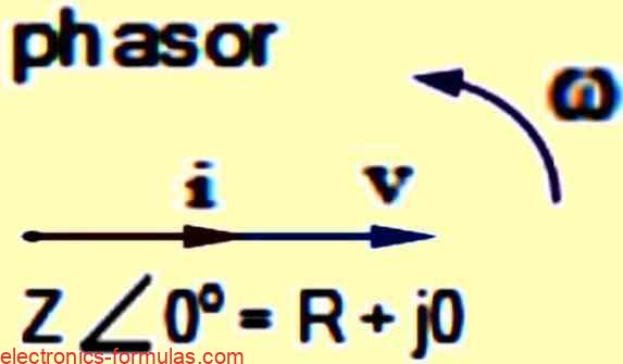
Since resistors don’t cause any phase shift between voltage and current waveforms, all the real power gets delivered directly to the resistance and converted into usable forms like heat, light, or mechanical work. This is why, real power is also considered the circuit’s average power.
Impact of Phase Angle (Φ): When Things Get Interesting
However unlike resistors, other components like capacitors and inductors introduce a phase shift (Φ) between voltage and current. This additional factor affects how real power is calculated in AC circuits.
Finding Real Power with Phase Angle
To account for the phase shift, the real power formula gets extended to:
P = I² * R = Vrms * Irms * cos(Φ) (W)
Here:
- Vrms is the root mean square voltage (V)
- Irms is the root mean square current (A)
Focusing on Resistive Circuits: Zero Phase Shift
However it’s important to remember that in a purely resistive circuit (with no capacitors or inductors), the phase difference between voltage and current is zero (Φ = 0°).
Therefore the cosine term (cos(Φ)) in the extended formula becomes 1, and the real power calculation simplifies back to P = I² * R, just like in DC circuits.
- P = Vrms * Irms * cosΦ
- cos(0°) = 1
- P = Vrms * Irms * 1
- ∴ P = Vrms * Irms
Real Power: The Workhorse of the Circuit
- Real power (P): Measured in watts (W) which represents the actual electrical power used to perform work in a circuit. It’s calculated using the formula P = I² * R, where:
- I is the root mean square (rms) current in amperes (A)
- R is the resistance of the circuit in ohms (Ω)
- Units: Real power is typically measured in watts (W), kilowatts (kW) or megawatts (MW).
- Positive Value: Real power (P) is always a positive value.
Understanding Reactive Power in AC Circuits
Reactive power (Q) also known as wattless power, plays a crucial role in AC circuits. It doesnt contribute to actual work performed in the circuit (like powering a light bulb) but it significantly impacts the phase shift between voltage and current waveforms.
Origins of Reactive Power: Inductors and Capacitors
Reactive power is linked to the reactance caused by inductors and capacitors. Reactance opposes the flow of current in a way that real power (P) doesnt. Unlike DC circuits, AC circuits have reactive power due to these reactive components.
The Push and Pull of Reactive Power
- Real Power vs. Reactive Power: Unlike real power which is consumed by the circuit to perform work, reactive power (Q) interacts with the circuit in a way which can reduce the availability of real power. This happens because, reactive power creates and removes magnetic fields (inductors) and electric fields (capacitors) within the circuit. This creates a struggle between reactive power and real power for control of the circuit.
- Capacitors vs. Inductors:
- Capacitors: These components are seen as “generators” of reactive power, because their stored electric field tries to control the voltage, pushing back against the source.
- Inductors: These components are seen as “consumers” of reactive power ,because their stored magnetic field tries to control the current, resisting changes in current flow.
The Takeaway: No Real Work Done
Importantly, both capacitors and inductors, constantly exchange power with the source, meaning they neither truly consume nor generate power in the traditional sense. As a result no real work is done using reactive power (Q).
Calculating Reactive Power
Similar to real power we can calculate reactive power using the formula:
Q = I² * X = Vrms * Irms * sin(Φ) (volt-amperes reactive, VAr)
Here:
- I is the root mean square (rms) current (A)
- X is the reactance of the circuit (Ω)
- Vrms is the root mean square voltage (V)
- Irms is the root mean square current (A)
- Φ is the phase angle between voltage and current
Reactive Power and the 90° Phase Shift
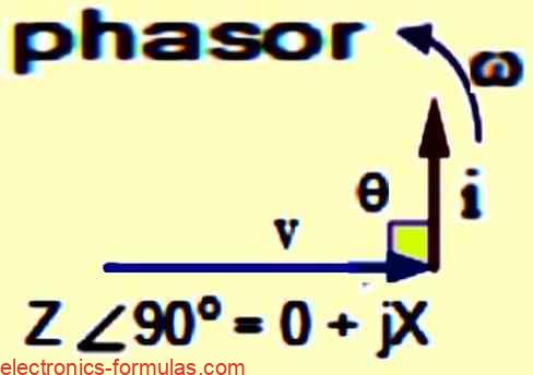
In a circuit, containing only a pure reactance (inductor or capacitor), the voltage and current waveforms experience a 90° phase difference.
Because of this.. multiplying the voltage (V) and current (I) by sin(Φ) results in a vertical component.
This is because, the sine function reaches its maximum value (1) at 90° which aligns with the 90° phase shift between voltage and current.
Consequently the resulting value represents the reactive power (Q) in the circuit, as shown in the below formula:
- Q = Vrms * Irms * sinΦ
- sin(90o) = 1
- Q = Vrms * Irms * 1
- Q = Vrms * Irms (VAr)
- Formula Breakdown: The above formula for reactive power (Q) uses:
- Q: Reactive power in volt-amperes reactive (VAr)
- V: Root mean square (rms) voltage in volts (V)
- I: Root mean square (rms) current in amperes (A)
- Φ: Phase angle between voltage and current (degrees)
- Reactive Power and Phase Shift: The formula highlights that, reactive power is the product of voltage and current multiplied by the sine of the phase angle (sin(Φ)). In a purely reactive circuit, (entirely capacitors or inductors), this phase shift is 90o, causing a maximum value for the sine function (1). However the formula can handle any phase angle (Φ) between voltage and current in general AC circuits.
- Units of Reactive Power: Reactive power is measured in volt-amperes reactive (VAr) and can be expressed in larger units like kilovolt-amperes reactive (kVAr) and megavolt-amperes reactive (MVAr) for larger power systems.
Understanding Apparent Power
We’ve already seen that real power (P) gets used by resistors, while reactive power (Q) interacts with capacitors and inductors. This interaction creates a phase difference between voltage and current waveforms, due to the interplay of these resistive and reactive components.
Complex Power and the Power Triangle
Theres a mathematical relationship between real power (P) and reactive power (Q) called complex power. However the total power delivered to an AC circuit isn’t simply the sum of real and reactive power, instead, it’s the vector sum of these two, represented in volt-amperes (VA) and visualized using the power triangle.
Apparent Power: The “Seeming” Total
The product of the root mean square (rms) voltage (V) applied to the circuit and the rms current (I) flowing through it gives us the “volt-ampere product” (VA) denoted by S. The magnitude of S is commonly known as; apparent power. This apparent power might seem like the total power consumed by the circuit, but it’s a bit misleading.
Why?… Because, apparent power (S) includes both the real power (P) that actually does work (represented by the in-phase component), and the reactive power (Q) which doesn’t directly contribute to work (represented by the out-of-phase component).
The Power Triangle
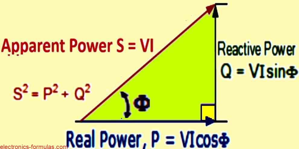
Identically, to the impedance triangle, the power triangle visually depicts the three key power components in an AC circuit:
- Horizontal (adjacent) side: Real power (P) in watts (W)
- Vertical (opposite) side: Reactive power (Q) in volt-amperes reactive (VAR)
- Hypotenuse: Apparent power (S) in volt-amperes (VA)
This right-angled triangle showcases the relationship between these three power elements providing a graphical understanding of power flow in AC circuits.
Power Triangle Breakdown
The diagram showcases a power triangle which is a valuable tool, for understanding the relationship between different types of power in an AC circuit.
- Real Power (P): Represented by the horizontal side is the actual working power in watts (W) calculated using P = I² * R.
- Reactive Power (Q): Represented by the vertical side is measured in volt-amperes reactive (VAR) and reflects the power exchange between the circuit and reactive components (capacitors and inductors). It doesn’t contribute to actual work.
- Apparent Power (S): This is the hypotenuse of the triangle and is calculated using S = I² * Z. Measured in volt-amperes (VA), this represents the total power delivered by the source which can be further divided into real and reactive power.
Phase Angle (Φ): This angle indicates, the phase difference between voltage and current waveforms. A larger phase angle signifies a greater presence of reactive power.
Relationship between Power Triangle Sides and Phase Angle:
- Cos(Φ) = P/S = W/VA: This highlights the connection between power factor, and the cosine of the phase angle.
- Sin(Φ) = Q/S = VAr / VA: This shows, how the sine of the phase angle relates to the ratio of reactive power to apparent power.
- Tan(Φ) = Q/P = VAr / W: This demonstrates the relationship between the phase angle’s tangent, and the ratio of reactive power to real power.
Understanding Power Factor
Power factor (p.f.) denoted by cos(Φ), is a critical parameter in AC circuits. It reflects how efficiently the circuit utilizes the delivered power.
Calculating Power Factor
Power factor is a dimensionless quantity, calculated as the ratio of real power (P) consumed by the circuit (in watts) to the apparent power (S) delivered by the source (in volt-amperes). This can be expressed as a decimal value (e.g., 0.95) or a percentage (e.g., 95%).
Power Factor and Phase Angle
Power factor is directly linked to the phase angle (Φ) between the voltage (V) and current (I) waveforms in the circuit. Here V and I represent the root mean square (rms) values of voltage and current. Interestingly… the order in which we calculate the phase difference (current with respect to voltage or vice versa) doesnt matter.
The Power Factor Formula
The mathematical relationship between power factor and the phase angle is represented by the formula:
- Power Factor = watts / volt-amperes
- = P / S = VIcosΦ / VI
- = cosΦ
Previously we had discussed that in a purely resistive circuit (containing only resistors), the voltage and current waveforms are perfectly aligned (in-phase) with a zero-degree phase difference (Φ = 0°).
This alignment results in all the delivered power being “real” power (P) used for work. Consequently the apparent power (S) and real power (P) become equal, leading to a power factor (p.f.) of:
- Power Factor (p.f.) = cos(Φ) = cos(0°) = 1.0
In this ideal situation the watts consumed (real power) match the volt-amperes consumed (apparent power), resulting in a unity power factor (1.0 or 100%).
This signifies maximum efficiency, because all delivered power gets used for work.
On the other hand we also saw that in a purely reactive circuit (containing only capacitors or inductors), the voltage and current waveforms are completely out-of-phase, expereincing a 90° phase difference (Φ = 90°).
With this significant phase shift, the power factor becomes:
- Power Factor (p.f.) = cos(Φ) = cos(90°) = 0
Here even-though there’s voltage and current flow, the real power consumed (P) is zero because the reactive power (Q) cancels it out. This highlights the inefficiency of purely reactive circuits.
Optimizing Power Factor
Reducing the reactive power component (VAr) in the power triangle has a direct effect on the phase angle (θ). Lowering the reactive power component shrinks the angle (θ) causing the power factor to get closer to unity (1).
Since, a high power factor indicates efficient use of delivered current, it’s desirable in most practical AC circuits.
Power Factor Formula
The relationship between real power (P), apparent power (S), and power factor (p.f.) can be expressed through the formula:
- Real Power (P) = Apparent Power (S) * Power Factor (p.f.)
- Power Factor (p.f.) = Real Power (P) in Watts / Apparent Power (S) in volt-amps
In AC circuits, the phase difference between voltage (V) and current (I) waveforms impacts the power factor (p.f.). Heres how:
- Inductive Circuits (Lagging Power Factor): When dealing with inductors, the current (I) lags behind the voltage (V). This phase shift is often remembered using the mnemonic “ELI” (Inductor, Lagging current). As a result these circuits have lagging power factor.
- Capacitive Circuits (Leading Power Factor): Conversely, capacitors cause the current (I) to lead the voltage (V). This phase difference can be remembered with the mnemonic “ICE” (Inductor, Capacitor, Leading current). Thus, these circuit exhibits leading power factor.
Solving a Power Triangle Problem
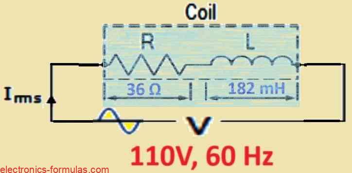
We have a coil with the following properties:
- Inductance (L): 182 millihenries (mH)
- Resistance (R): 36 ohms (Ω)
This coil is connected to an AC power supply with the following specifications:
- Voltage (V): 110 volts (V)
- Frequency (f): 60 Hertz (Hz)
We’ re interested in solving four parts related to this AC circuit:
(a) Impedance (Z): Calculate the total impedance of the coil which considers both its resistance and inductive reactance.
(b) Current (I): Determine the current flowing through the coil, based on the voltage and impedance.
(c) Power Factor (pf): Find the power factor… a parameter indicating how efficiently the circuit utilizes the supplied power.
(d) Apparent Power (S): Calculate the apparent power which represents the total volt-amperes delivered by the source.
Additionally we want to visualize the relationship between these power components, by drawing the resulting power triangle. This triangle helps us, to understand the inter-play between real power (performing work), reactive power (stored/returned by reactive components), and apparent power.
- R = 36 Ohms
- XL = 2πfl = 2 * 3.14 * 60 * 182 * 10-3 = 68.57 Ω
- Z = √(R2 + X2L) = √362 + 68.572 = 77.44 Ω
Now, let us find how much current the coil consumes:
- V = I * Z
- ∴ I = V / Z = 110 / 77.44 = 1.42 Arms
Next, we calculate the power factor and the phase angle Φ:
- cosΦ = R / Z, or sinΦ = XL / Z or tanΦ = XL / R
- ∴ cosΦ = R / Z = 36 / 77.44 = 0.46
- cos-1(0.46) = 62.30° (lagging)
Next, we will calculate how much Apparent power (S) was consumed by the coil:
- P = V * I * cosΦ = 110 * 1.42 * cos(62.30°) = 72.60 Watts
- Q = V * I * sinΦ = 110 * 1.42 * sin(62.30°) = 137.45 VAr
- S = V * I = 110 * 1.42 = 156.2 VA
- or S2 = P2 + Q2 =
- ∴ S = √(P2 + Q2) = √72.602 + 137.452 = 155.44 VA
Now, let’s draw the power triangle for the coil, as shown below:
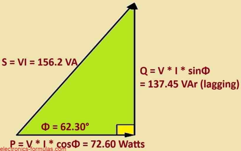
As the power triangle relationships of this simple example demonstrates, at a power factor of 0.46 or 46%, the coil requires 156.2 VA of apparent power to produce only 72.60 watts of real, usable work. In other words at 46% power factor, the coil takes about 70% more current to do the same work. This is significant amount of wasted current that doesnt contribute to actual work.
Conclusion
Power in AC Circuits
In this article we saw, how the 3 key players in AC power – real power (P), reactive power (Q), and apparent power (S) can be visualized using a right angled triangle called the power triangle. The sides of this triangle represent these power components, and their relationship is expressed by the formula:
S² = P² + Q²
Here:
- P: Real power in watts (W) indicates the actual power used for work
- Q: Reactive power in volt/amperes reactive (VAR) indicates power exchanged between the circuit and reactive components (inductors and capacitors) and not used for work
- S: Apparent power in volt-amperes (VA) indicates the total power delivered by the source
Power Factor
We also learned the concept of power factor (p.f.). This crucial parameter indicates, how efficiently an AC circuit utilizes the delivered power. Its calculated as the ratio of real power (P) consumed by the circuit to the apparent power (S) supplied by the source. Mathematically this transforms to:
Power Factor (p.f.) = Real Power / Apparent Power = W / VA
Power factor, is typically expressed as a decimal (e.g., 0.95) or a percentage (e.g., 95%).
The Power Factor Angle
The cosine of the phase angle (Φ) between the current and voltage waveforms in the circuit is directly related to the power factor. Heres the connection:
- Unity Power Factor (1.0 or 100%): When the power factor is 1.0 (unity), the real power consumed equals the apparent power. This signifies that, a zero-degree (0°) phase difference (cos-1(1.0) = 0°). In this ideal scenaro, all supplied power is used for work resulting in maximum efficiency.
- Zero Power Factor (0%): A power factor of zero indicates a 90° phase difference (cos-1(0) = 90°) between voltage and current. In this case, even though theres current flow, the reactive power cancels out the real power, causing zero actual power consumed by the circuit.
Power Factor in Real-World Circuits
In practical AC circuits, the power factor can range from 0 to 1.0, depending on the type of load connected.
- Inductive-Resistive Circuits (Lagging Power Factor): Most AC circuits are inductive-resistive, meaning, they contain both inductors and resistors. In these circuits, the power factor is “lagging,” indicating the current lags behind the voltage.
- Capacitive-Resistive Circuits (Leading Power Factor): Circuits with capacitors along with resistors exhibit leading power factor, where the current leads the voltage.
Importance of Power Factor
A low power factor (closer to 0) signifies wasted power and reduced efficiency. This is because, a circuit with a low power factor necessitates a higher current to deliver the same amount of real power compared to a circuit with a high power factor (closer to 1.0 or unity). Thus, improving the power factor causes a more efficient utilization of power in AC circuits.
References: Power Triangle
Leave a Reply