
Compared to the Hartley oscillator that we looked at in the last lesson, the Colpitts oscillator represents a very different way of designing tuned tank circuits. Similar to the Hartley oscillator which creates a sinusoidal output waveform by implementing an LC resonance sub-circuit between the collector and base of a single-stage transistor (BJT) amplifier, the Colpitts oscillator also uses an LC resonance sub-circuit arrangement.
But, the main characteristic that sets the Colpitts Oscillator apart is that it employs a capacitive voltage divider network to achieve the center tapping of the tank sub-circuit, which just the opposite to the tapped autotransformer-style inductor used in a Hartley oscillator. This striking difference in the design approach results in a radically different oscillator arrangement, one that demands more investigation and examination.
Tank Circuit Arrangement

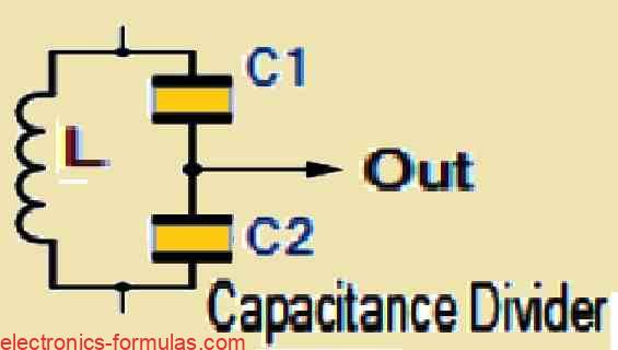
In its most basic form, the Colpitts oscillator functions depending on a capacitive voltage divider network for getting the feedback. As seen in the image above, two capacitors, indicated by C1 and C2 are strategically placed across a single common inductor L. This resulting combination of C1, C2, and L produces a tuned tank circuit in which the oscillation condition can be accurately defined through the equation XC1 + XC2 = XL, which looks quite identical to the condition observed in the Hartley oscillator.
The significant benefit of this capacitive circuit arrangement comes in the minimization of self- and mutual inductance within the tank circuit, hence boosting the frequency stability of the oscillator while simultaneously simplifying the overall design.
In an arrangement equivalent to the Hartley oscillator, the Colpitts oscillator also makes use of a single-stage bipolar transistor amplifier as its gain component for generating a sinusoidal output waveform. To understand this, you can refer to the following shown circuit diagram.
Understanding a Basic Colpitts Oscillator Circuit

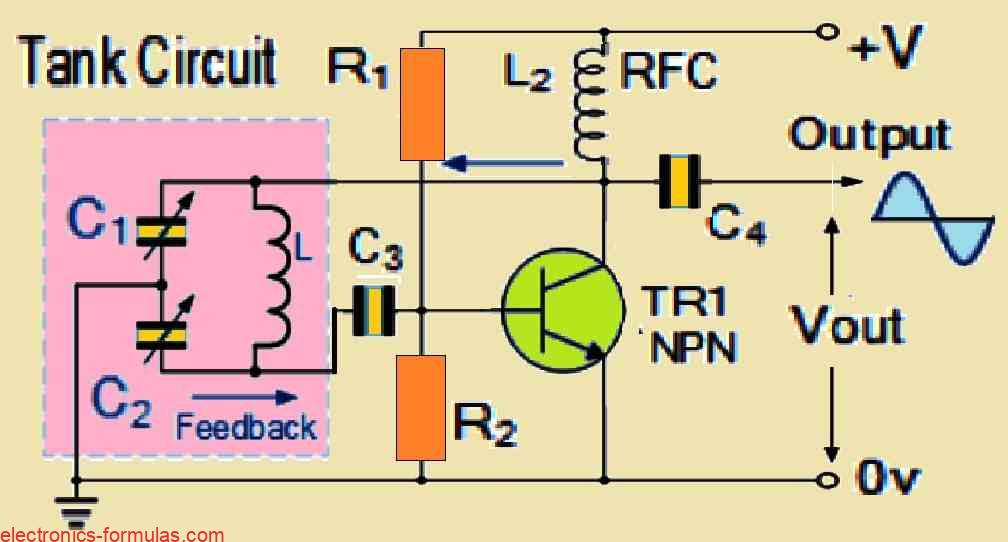
We can see two capacitors C1 and C2, which are configured in series and serve as a basic voltage divider, are hooked up to the base terminal of the transistor. When we switch ON the power supply initially, capacitors C1 and C2 undergo a charging process and then a subsequent discharging through the coil L, which results in the generation of oscillations across the capacitors. These oscillations are then subsequently applied to the base-emitter junction of the transistor which finally appear in an amplified form at the collector output of the transistor.
In accordance with standard design procedures, the resistors R1 and R2 supply the transistor with the normal stabilizing DC bias. In the meantime, the additional capacitors act as bypass capacitors for DC-blocking, making sure that any unwanted DC components are not interfering with the oscillations it produces
To enable the initial start of the oscillations, a radio-frequency choke (RFC) is added to the collector side of the BJT in the circuit. This choke demonstrates a low resistance at DC voltages and a high reactance, ideally an open circuit, at the oscillation frequency (fr).
In order to accomplish the required external phase shift, a similar technique found in the Hartley oscillator circuit is used here, which provides the essential positive feedback for a long-term undamped oscillations.
C1 and C2 are usually “ganged” together to generate a consistent quantity of feedback, therefore the ratio between them determines how much feedback can be actually generated. This configuration allows for the adjustment of the value of one capacitance while the value of the other capacitor adjusts simultaneously on its own since both are “ganged”, guaranteeing a constant amount of feedback during the oscillation process.
As determined by the resonance frequency of the LC tank circuit, the oscillation frequency of a Colpitts oscillator can be calculated as follows:
f = 1/2π√(LCT)
In the above formula: 1/CT = 1/C1 + 1/C2 which can be simplified as: CT = (C1 * C2)/(C1 + C2)
The configuration of the transistor amplifier can be characterized as a Common Emitter Amplifier, in which the output signal demonstrates a precise 180° phase shift with respect to the input signal. In order to achieve an additional 180° phase shift required for oscillation, the two capacitors, C1 and C2, are connected in series and in combination together with the inductive coil, which leads to an overall phase shift of either zero or 360°.
How strong the feedback signal could be, varies depending on the values of C1 and C2. A more thorough investigation shows us that the voltage across C1 is the same as the output voltage of the oscillator Vout, while on the other hand the voltage across C2 is equivalent to the oscillator’s feedback voltage. This means the voltage across C1 will be much bigger than that across C2.
It is possible for us to simply adjust the values of the capacitors C1 and C2 to control the amount of feedback voltage that is supplied back to the tank circuit. Despite this, it is important that you understand that if we introduce too much feedback, that might distort the output sine wave, and if we make the feedback signal too small that would cause the circuit to stop oscillating.
Basically the amount of feedback produced by the Colpitts oscillator depends on the capacitance ratio between C1 and C2, which is the most important component in determining how excited the oscillator is going to be. The ratio of these two is known as the “feedback fraction” and this may be represented mathematically through the following formula:
Feedback Fraction: (C1/C2)%
Solving a Colpitts Oscillator Circuit Problem
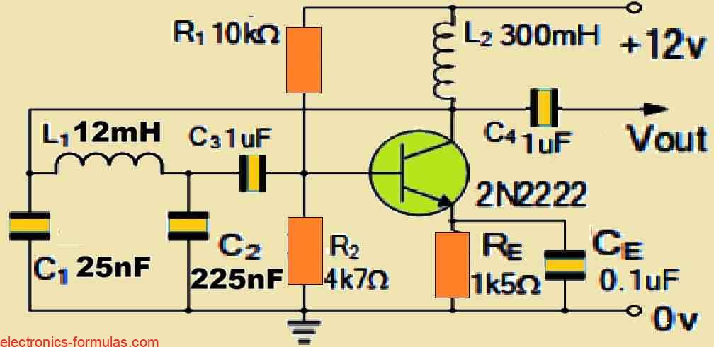
We have a Colpitts Oscillator circuit built with two series capacitors each having a value of 25nF (C1) and 225nF (C2) respectively which are connected in parallel with a 12mH inductor coil (L). Calculate the frequency of oscillations of the circuit and the feedback fraction and also draw the resultant circuit.
First we need to calculate the frequency of oscillation of the circuit using the following formula:
fr = 1/2π√(LCT)
Since we have two capacitors connected in series in our Colpitts oscillator design, the total capacitance of the series configuration becomes:
CT = (C1 * C2)/(C1 + C2)
= (25 * 225)/(25 + 225)
= 22.5 nF
Now, since the value of the given inductor is 12 mH, solving the previous equation for the frequency of oscillations gives us the following results:
fr = 1/2π√(LCT)
= 1/[2 * 3.14 * √(0.012 * 22.5 * 10-9)]
= 9690 Hz = 9.69 kHz
So, the frequency of oscillation for our Colpitts Oscillator design will be around 9.69 kHz, and now we cal calculate its feedback fraction using the following formula:
FF = C1/C2 = 25/225 = 11%
As per the results obtained from the above calculations, it is now possible for us to draw the resultant Colpitts Oscillator circuit diagram, as shown below:

Designing a Colpitts Oscillator using an Op-amp
Just like the Hartley oscillator that we studied in the previous tutorial, it is easy for us to construct the Colpitts oscillator using either a bipolar junction transistor (BJT) or an operational amplifier (op-amp) as the active oscillatory stage.
When we use an op-amp then the working theory and principles of the Colpitts oscillator remain exactly the same, and we can calculate the frequency of oscillation using the same set of formulas which we used for the transistorized version.
Circuit diagram

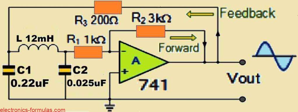
It is important to note that the operational configuration of the Op-amp based Colpitts Oscillator is actually just an inverting amplifier arrangement, with the amplification coefficient determined by the ratio of the resistors R2 to R1. In this design oscillations or the frequency will get triggered and begin only when the minimum gain of the amplifier is 2.9, any lower amplification than this would cause the oscillations to become unsustainable. Next, let us now understand the role of the resistor R3, this resistor is critical in supplying the necessary feedback to the LC tank circuit, which actually initiates and enables the oscillation process.
You will find that a Colpitts oscillator circuit has plenty of distinct advantages which may not be available with an Hartley oscillator design. Using a Colpitts oscillator circuit would allow you to get a more accurate and a pure form of sinusoidal waveform, which is mainly because of the low impedance pathways enabled by the capacitors at high frequencies. Furthermore the capacitive reactance properties of these capacitors facilitate an FET-based Colpitts oscillators to operate at extremely high frequencies.
However there is one important thing that you must consider, always make sure to select an op-amp or FET amplifying device that is correctly rated to function at these extremely high frequencies, if not selected correctly the oscillations could become distorted or unsustainable.
The Colpitts Oscillator: A Recap
The Colpitts Oscillator is made up of a parallel LC resonator tank circuit which includes a capacitive divider network working as the feedback mechanism. It is important to note that the Colpitts oscillator can be created in many different forms, the most common of which is a transistorized circuit similar to the one above which we discussed.
The most important element of the tank sub-circuit is its center tapping, which is placed carefully at the intersection of a network of capacitive voltage dividers to allow for a fraction of the output signal to feed back to the transistor’s emitter terminal.
Together, the two capacitors connected in series create a 180-degree phase shift which is then reversed by another 180-degree phase shift to provide the necessary positive feedback for the circuit. The resonance frequency of the tank circuit determines the frequency of oscillation which is characterized with a cleaner and nice looking sine-wave voltage.
In our next forthcoming tutorial on oscillators, I will talk more about RC Oscillator designs in which we will utilize resistors and capacitors as the tank circuit to produce a sinusoidal waveform, this tutorial might help you to extend your understanding of oscillator circuits and also regarding their applications.
References: Colpitts oscillator