So here we are talking about controlling lamps, motors, heaters and other similar loads using devices like thyristor and triac, right? Both these devices, thyristor and triac can actually do this job like switch ON/OFF or adjust power for these loads. But then we must know one big issue when we try to use thyristor for this.
That problem is, this thyristor it is like a diode only. Means it is a unidirectional component, OK? So it allows current to move only in one direction – that is from Anode to Cathode – it will not allow current to flow in reverse side.
Now this is fine when we use it in DC circuits because in DC we already have current flowing only in one direction so once we trigger this thyristor ON, then it stays ON and all DC power just goes straight to the load.
But now if we try to use this thyristor in an AC circuit – like with 230V mains or other sinusoidal AC – then we get problem. Because in AC, current keeps changing direction every half cycle.
But our thyristor only allows current in one direction. So, it will only conduct during positive half cycle when Anode becomes positive. In the negative half, even if Gate is getting signal, thyristor will remain OFF.
So what happens? It behaves just like a half-wave rectifier and only gives power in one side of AC cycle. That means, our load is getting only half the power.
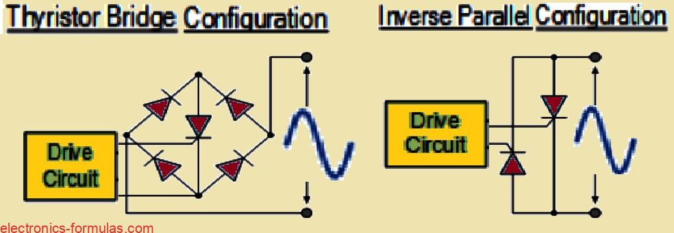
So then if we want full power or full-wave AC control using thyristors, we have to use some extra trick. One idea is, we can put one thyristor inside a full-wave bridge rectifier circuit, so it gets positive pulses in both half cycles and we can trigger it properly.
Another method is, we can connect two thyristors in reverse-parallel (means back-to-back) so that one handles positive half, other handles negative half. This way both directions get covered.
But both these ideas will increase total number of components and wiring also becomes more complex. So circuit becomes little more bulky and complicated.
Analyzing Triac Circuit Topologies
So, What is a Triac Actually?
Now apart from thyristor and SCR, there is one more solid-state device which also belongs to thyristor family only. We call this one “Triode AC Switch” or short form – Triac. It is also used like a power switch in electronic circuits. But then the biggest plus point with triac is that it is bidirectional, not like thyristor which was one-way only.
Bidirectional Triggering – Main Feature of Triac
So what this means is, a triac can conduct current in both directions. It does not matter if voltage at its terminal is positive or negative or even if gate pulse is positive or negative. It will trigger and start conducting in both cases. That is why we say triac is a two-quadrant gate-controlled switch because both main terminal and gate can get triggered by both polarities.
How Triac is Built Internally
OK now if we look deeper into triac working, we will see that this device behaves like two thyristors joined back-to-back or what we call inverse parallel connection. But instead of using two separate thyristors outside, this whole arrangement is packed inside one single three-pin body. Also both the internal thyristors are sharing same Gate pin, so only one Gate terminal is needed.
Terminal Names: No Anode, No Cathode Here
Now because triac can work both ways, we cannot use the names Anode and Cathode like we do in normal thyristor. Instead we use different names for the main terminals, we call them MT1 (Main Terminal 1) and MT2 (Main Terminal 2). And Gate pin is still called G, like usual.
So in AC circuits, the gate connection of triac is normally done with respect to MT1, just like how thyristor gate is connected with respect to cathode. It is also a bit similar to how base and emitter are arranged in a transistor.
Construction, Layers and Symbol of Triac
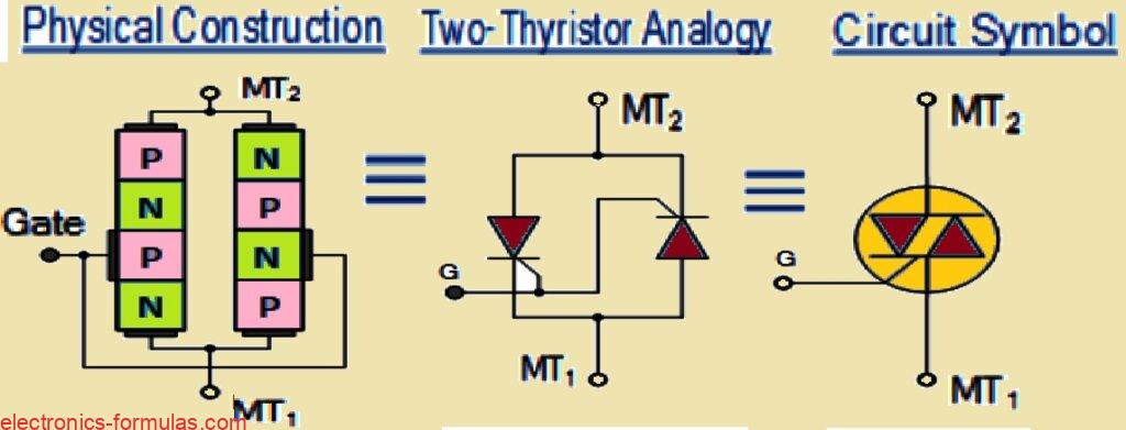
Now inside the body of the triac, the construction has special P-N layer doping because it needs to handle both directions of current. Also the circuit diagram symbol of the triac looks like two thyristors placed in reverse directions and sharing a gate… we can recognize it easily.
How a Triac is Built Inside – Layer Talk
So now we already know that this triac thing is a bidirectional three-terminal power device, right? Now let us look little deeper into how it is made from inside. So basically it is made using four-layer structure when it is conducting in positive direction, the layers go like PNPN, and when conducting in negative direction, the layer sequence becomes NPNP. This switching between both structures makes it special.
OFF State Behavior – Like an Open Switch
Now when triac is not triggered then it behaves just like an open-circuit switch. It blocks current from flowing, no matter which direction. So in this OFF condition, triac works like a normal open switch, fully blocking AC or DC current… just sits quietly doing nothing.
ON State – Gate Pulse Starts the Show
But then once we give a small gate triggering pulse, the triac jumps into conduction mode. And now here comes the fun part, it does not care about the direction of current,. Whether current is going from MT2 to MT1 or reverse from MT1 to MT2, triac will allow both.
The Four Triggering Modes of Triac – Very Important
Now because this triac is symmetrical and can conduct in both current directions and also can accept both positive and negative gate signals, so it actually has 4 different ways or modes to get triggered ON.
Here are the 4 modes:
- Mode I+:
- MT2 current = Positive (+ve)
- Gate current = Positive (+ve)
- This is most sensitive mode and triggering is easy.
- Mode I–:
- MT2 current = Positive (+ve)
- Gate current = Negative (–ve)
- This mode also works but needs little more gate current.
- Mode III+:
- MT2 current = Negative (–ve)
- Gate current = Positive (+ve)
- This works in reverse cycle of AC with positive gate.
- Mode III–:
- MT2 current = Negative (–ve)
- Gate current = Negative (–ve)
- Least sensitive mode, needs strong gate triggering.
Shown in I-V Characteristics Curve of Triacs
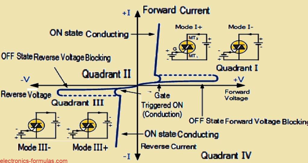
So all these 4 triggering modes, we can actually see them clearly in the I-V characteristics graph of the triac. The graph shows how the voltage and current behave in each quadrant when gate pulses are applied in different combinations. It helps us to understand how triac turns ON and how much gate current is needed in each case.
Triggering the Triac in Different Quadrants
So when we are using a triac, especially in Quadrant I, then most common way to trigger it is by giving a positive gate current. This method is called mode I+ and it is the easiest and most sensitive one.
But then even in Quadrant I, we can also use a negative gate current to turn the triac ON and this one is called mode I–. So both positive and negative gate currents work here, though I+ is more preferred.
Same in Quadrant III – Modes III+ and III–
Now in the negative half of the AC cycle, that is Quadrant III, we also have two gate triggering options. One is with negative gate current, called mode III–, which again is more commonly used. The other one is mode III+, where we use positive gate current in the negative current region.
So in total we got all four modes:
- I+
- I–
- III+
- III–
Out of these, I+ and III– are more sensitive and reliable so they are used more times in circuits…
I– and III+ Need Stronger Gate Current
But then modes I– and III+ are not that sensitive. These ones need more gate current to fire the triac ON properly. So we have to push more signal into the gate to make it respond, compared to I+ or III– which work even with smaller gate pulses.
Holding Current Needed – Just Like SCR
Now just like SCRs, our triac also needs a small amount of current called holding current (IH) to stay in conduction. Especially around the zero-crossing point of the AC waveform, this holding current becomes important. If current drops below IH, the triac will turn OFF automatically.
Even Though It Looks Like One Device
So even though triac looks like a single device from outside, remember that internally it is like two thyristors back-to-back. Because of this, the two sides can show different electrical behavior, like:
- different breakdown voltages,
- different trigger voltage levels,
- and also different holding current values.
So even if it is one package, it still acts a bit like two separate SCRs packed together. That is why we must test and use triac carefully, especially when we want clean switching across full AC cycle.
Where We Use Triac – Applications in Real Life
So now when we look at where this triac is used, we can say it is one of the most used semiconductor parts for switching and controlling AC power. The main reason behind this is, triac can be switched ON using either a positive or a negative gate pulse, and this works no matter what side the AC voltage is at that moment.
So then, if AC waveform is in positive half cycle or even negative half cycle, this triac will still trigger properly. It does not care about the supply polarity. That makes it super useful for controlling AC loads, like if we want to dim a lamp or adjust speed of an AC motor or control a heater or fan… triac can do all of that.
Because of this bidirectional ON behavior, we can build a very simple AC control circuit using just one triac. The gate pulse can come from any low-power source and still, it can control big AC loads without any trouble.
Understanding Fundamental Triac Circuits
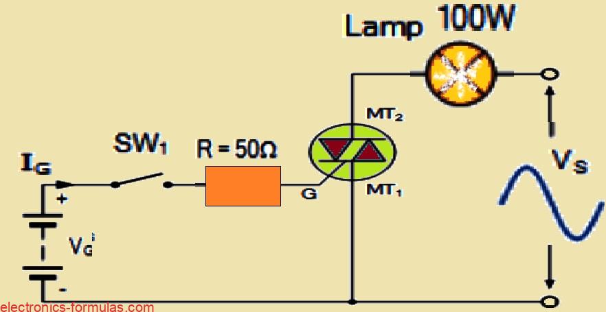
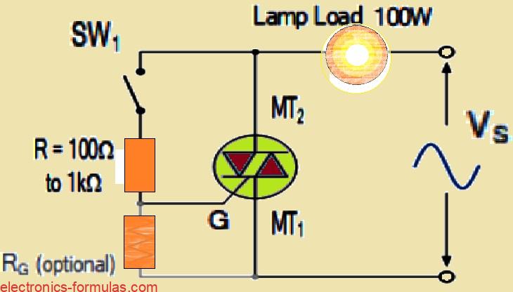
Now above we seeing one very basic and easy type DC triggered triac power switching circuit. That one diagram above showing how it working. When that switch SW1 is in open condition then nothing going into triac Gate pin, right? So then no gate current happening and that time this triac not firing, and that lamp also staying OFF only.
But suppose we closing that switch SW1 then one gate current starting to flow from battery side (we calling that VG) through that resistor R, and going straight into triac Gate.
So what happen now? That triac getting triggered and going into full conduction mode. It behaving just like one closed switch. So because of this, now that lamp starting to take full power from that AC mains, which is sinusoidal supply.
Now one important thing, here that battery always giving positive gate current whenever we closing SW1. So that means this triac getting gate signal properly during mode I+ and also during mode III+, no matter what is the polarity of that MT2 terminal. So it not caring about whether MT2 going positive or negative, this DC gate signal always keeping triac ON during those modes.
But bro, one small problem coming here. For this circuit to work nicely, we must give extra gate supply – like one separate DC voltage, either positive or negative, to fire that triac properly. That extra source we needing always. So it becoming not so convenient sometimes.
But good thing is, we not always needing to use extra gate supply. We can even use that same AC supply voltage for giving gate triggering signal.
Means that AC voltage which going to lamp, same we can use to trigger that triac also. So this saving us from using battery or DC supply. Let us now see one different circuit below which doing this AC triggering trick.
Basic Triac Switching Circuit – ON and OFF AC Power Control
So here we can see that we got one simple triac circuit, right, and that triac is used like a static switch for controlling AC power. This one is giving just plain “ON” and “OFF” action like how we did before with DC switching circuits. Nothing but just simple ON/OFF.
Now when that switch SW1 is in open condition then what happens? Then that triac is behaving like it is an open circuit, means totally OFF. So the AC current is not able to reach the lamp, right? That is why lamp is getting zero current, so no light, nothing.
But then when we close that switch SW1 then story changes. That gate of triac is now getting triggered through the resistor R which is actually working like a current limiting resistor. So it is not allowing excess current to hit the gate.
Now once the gate gets the correct trigger, triac turns ON then we also say it is getting “latched”. That latching is happening shortly after each half-cycle of the AC starts. So now it is sending full power through to the lamp load, means lamp is glowing properly.
What Happens During Each AC Cycle
Now we have to remember that this supply is not DC, it is sinusoidal AC, which is always going up and down, positive and negative, half-cycles. So because of this nature of AC, this triac has one more behaviour.
At the end of every half cycle, the voltage of AC is going down to zero, right? So in that moment, the current through the load also becomes zero. So what happens then? The triac is automatically getting “unlatched”. That means it stops conducting on its own. No need to do anything.
But again when the next half-cycle starts and if the SW1 is still closed then again the gate gets triggered and triac is getting latched once more — but now the other half of the triac conducts (because it has two thyristors inside, back-to-back). So the triac again starts passing full current.
So this ON/OFF triggering keeps happening again and again on both sides of the AC waveform — positive and negative, as long as switch SW1 is kept closed.
This whole process we call full-wave control because both halves of the sinewave, the full wave are getting controlled by the triac.
Taking the Triac Switching Further – Gate Control
Now one more important thing, this triac is nothing but like two SCR’s connected in opposite direction internally, back-to-back. So we can actually play around with how we give the gate triggering.
If we change or modify the way gate is getting fired then we can get more control over the switching. That means not just ON/OFF but more complex control like phase control or dimming can also happen.
We will see how to do that in next part of the circuit below.
How Lamp Works with Switch Positions A B and C
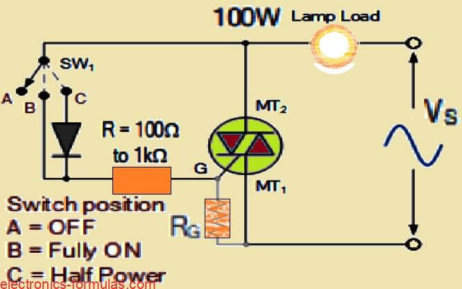
Like we saw before if we keep that switch SW1 open at position A then no gate current will flow into the triac. That means the lamp is going to stay completely OFF. Nothing happens there.
But now if we move that switch to position B then gate current will start flowing during every half cycle. That gate triggering happens just like how it was happening before. So triac starts conducting in both mode I plus and mode III minus. That way full power goes to the lamp and the lamp glows with full brightness.
Now if we shift that switch to position C then that diode will come into action. That diode is placed in such a way that it blocks the gate current when MT2 becomes negative. That time diode becomes reverse biased, so it stops that gate current. So triac does not conduct during negative half cycles.
Because of this conduction happens only during the positive half cycles. So that is mode I plus only. That means only half power goes to the lamp. So lamp will glow, but with half brightness.
So depending on where we keep the switch, the lamp can be fully OFF or glowing with Half Power, or glowing with Full Power.
Triac Phase Control for AC Power
Now we talk about another method which we call Triac Phase Control. This method is very commonly used when we want to control the switching by cutting phase of AC signal. That way we can vary how much voltage is going to the load. So that also means we can control the power to that load.
We mostly use this method with motors or other AC devices. In this case we can control both positive and negative halves of the input waveform.
So this AC motor speed control works by adjusting the firing angle. That gives us fully variable and very linear type of control. Because of this we can change voltage from complete zero to full applied AC voltage. That range is smooth and controllable like shown in waveform.
How the Basic Phase Triggering Circuit Works
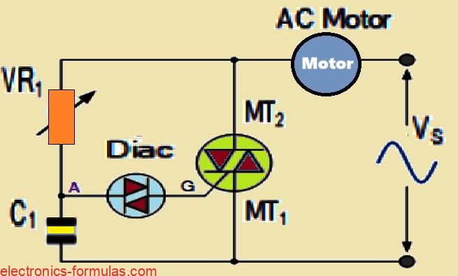
So in this basic phase triggering type circuit, we are using one triac device which we are putting in series with the AC motor.
Then we are connecting this series combination directly across the AC mains supply which is sinusoidal in nature.
Now to control the phase angle, we are using one variable resistor which we are calling VR1. This VR1 is used for adjusting how much delay we want to give to the gate triggering of the triac.
Because of this gate delay, we can control when the triac turns ON in each AC half cycle. That is how we are actually controlling the voltage that reaches to the motor. When we adjust VR1, then we change the phase angle, and then the motor gets more or less power depending on that.
How the Triac Gets the Trigger
The triac does not get the gate voltage directly. It gets it through a combination of VR1 and capacitor C1. These two components are working together to build up a voltage slowly. Now in between this path, we are putting one diac also.
The diac is one special bidirectional semiconductor part. That means it can conduct in both directions, and it also helps us to create a very sharp and sudden pulse which is very important for triggering the triac properly.
How Charging and Triggering Happens
At the starting point of every AC cycle, the capacitor C1 starts charging through the variable resistor VR1. This charging process keeps going until the voltage across C1 becomes equal to the breakdown level of the diac.
When that happens then the diac suddenly turns ON and allows the capacitor C1 to release its stored charge directly into the gate of the triac. Because of this sharp discharge pulse, the triac gets triggered and enters conduction mode.
What Happens After the Triac Turns ON
Once the triac gets its gate pulse and turns ON, then it becomes fully conducting and enters the saturation state. Now the triac itself starts conducting the full load current and takes over the entire operation.
At this point, the gate triggering components like VR1 and C1 do not matter anymore because the triac is already ON. So during the rest of that AC half cycle, the triac stays ON and supplies power to the motor.
Process Repeats in Every AC Cycle
Then when the AC half cycle reaches zero crossing point, the triac automatically turns OFF by itself because there is no more current flow.
So in the next AC half cycle, again the same process repeats. That means again C1 starts charging through VR1, and again the diac breaks down and fires the triac. So this keeps happening in every half cycle continuously.
Triac is Not Always Fully Symmetrical
But there is one thing we have to understand clearly. That is, the triac does not always trigger exactly the same way in both positive and negative cycles.
This is because in some conduction modes like mode I plus and mode III minus, the gate current requirement is different.
So the triac behaves in an asymmetrical way. That means sometimes the triggering angle may shift slightly between positive and negative sides of the AC waveform.
Applications of This Circuit
This type of basic triac speed control circuit is not only useful for controlling AC motors. We can also use the same idea for controlling brightness of incandescent lamps, or for regulating the power in electrical heaters.
Actually this kind of circuit is very similar to the common triac dimmer that we see in many household applications for controlling light brightness. But we must not use a standard commercial triac dimmer for controlling motors, because those dimmers are made for resistive loads only like filament bulbs, not for inductive loads like motors.
Conclusion Triac Operation
So now we can just do a quick summary of what we understood. A triac is a type of thyristor which has three terminals and four semiconductor layers. It is similar to SCR but it can work in both directions. The triac can be triggered in four different ways, but out of those two ways are more reliable and commonly used.
We can use triac for controlling AC power very effectively, especially when we are working with resistive loads like heaters, light bulbs, or small universal type AC motors that are found in portable tools and appliances.
Important Safety Advice
Now we must remember this last important thing. Since triac circuits are directly connected to high voltage AC mains, we should never do testing or touching when it is powered. If we want to check or modify the circuit then we must first disconnect it completely from the mains supply. Safety always comes first, and we should never ignore it.
Sources:
Thyristor, Triac Tutorial || Phase Angle Control
Leave a Reply