
In digital logic circuits, a “Logic OR Gate” functions depending on the specific conditions we apply to its input to produce its output which is written as Q. We get a LOW output from an OR gate only when all of its inputs are applied with a LOW state (logic level “0”), and if any of its inputs are HIGH (logic level “1”), the output will be HIGH.
In mathematically terms, the OR operation is represented by a Boolean expression involving logical addition which is denoted by a plus sign (+). For a two-input OR gate the Boolean expression is given by:
A + B = Q
This indicates that the output Q will be HIGH if either input A, input B, or both inputs are HIGH.
We call an OR gate as “Inclusive OR Gate” because it produces a TRUE output when at least one of its inputs is TRUE. To be precise, we can summarize the behavior of a two-input OR gate as stated below:
“If either input A or input B (or both) are TRUE, then the output Q is TRUE.”
2-input Transistor OR Gate
It is for us to create a simple 2-input inclusive OR gate by using RTL Resistor-transistor switches, which may be connected with each other in the manner shown below where the inputs can be seen connected directly with the baes of the BJTs. At least one of these BJTs must be turned ON into saturation for generating an output at Q.

We can create Logic OR Gates by configuring digital circuits to generate the required logical function and attribute a symbol whose shape expresses the logical operation of the OR function.
Types of Digital Logic “OR” Gate
The 2-input Logic OR Gate
Symbol

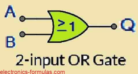
Truth Table
| B | A | Q |
| 0 | 0 | 0 |
| 0 | 1 | 1 |
| 1 | 0 | 1 |
| 1 | 1 | 1 |
The 3-input Logic OR Gate
Symbol

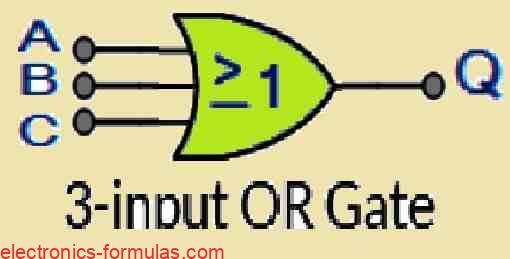
Truth Table
| C | B | A | Q |
| 0 | 0 | 0 | 0 |
| 0 | 0 | 1 | 1 |
| 0 | 1 | 0 | 1 |
| 0 | 1 | 1 | 1 |
| 1 | 0 | 0 | 1 |
| 1 | 0 | 1 | 1 |
| 1 | 1 | 0 | 1 |
| 1 | 1 | 1 | 1 |
Similar to the AND gate, we can have any desired number of specific inputs for an OR function, but, the types of OR gates that we commonly get from the market may have only 2, 3, or 4 inputs. If you want to add any more number of inputs then you might require the gates to be joined together in the cascaded manner, as shown in the following example:
OR Gate with Multiple-Inputs


Therefore we can express the above 6-input OR gate through Boolean language as:
Q = (A+B)+(C+D)+(E+F)
Alternatively, we can also express it in this way:
A OR B OR C OR D OR E OR F gives Q
When the number of inputs is odd, we can ensure that any “unused” inputs remain LOW by directly grounding them through appropriate “pull-down” resistors.
The OR gate ICs that we commonly find available in the market are as given below:
| Type | Part Number | Configuration |
|---|---|---|
| TTL Logic OR Gates | 74LS32 | Quad 2-input |
| CMOS Logic OR Gates | CD4071 | Quad 2-input |
| CD4075 | Triple 3-input | |
| CD4072 | Dual 4-input |
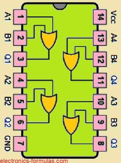
Pinout Diagram of the IC 7432 which is an an example of a Quad 2-input Logic OR Gate

In our next tutorial, which will deal with Digital Logic Gates, I will explain the digital logic NOT Gate function which can be implemented in TTL logic circuits as well as the CMOS logic circuits, and I will also explain about its Truth tables and its Boolean Algebra definition…. stay tuned.
References: OR Gate