Now in this tutorial we are going to learn in deep about one very important power electronic device called thyristor or also called Silicon Controlled Rectifier (SCR). We will try to understand how it is built and how it works. This thyristor is kind of similar to a transistor but still it is different in many ways.
It is actually a multi-layer semiconductor device and that is why in the name we have the word “silicon”. Now to switch this device ON, we need to give it one gate signal, that is why the word “controlled” is there. And once it turns ON, it behaves like a normal diode which can rectify current, that is why we call it “rectifier”.
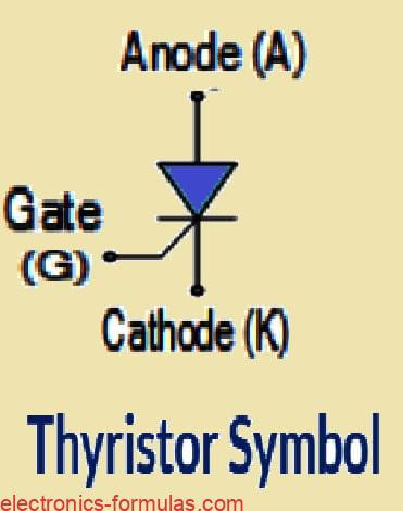
Even the symbol of thyristor also looks like one diode with a small gate input which clearly shows that it is nothing but a controlled diode. But now if we compare it with a diode or a transistor then it is more complex.
A normal diode has only two layers (P-N) and a bipolar transistor has three layers (P-N-P or N-P-N) but this thyristor has four layers arranged like P-N-P-N. So it has three PN junctions inside which makes it behave in a very unique way.
How the Thyristor Actually Works
Just like a diode, this thyristor is also unidirectional, that means it will allow current to flow only in one direction, from anode to cathode. But unlike the diode, this device does not start conducting by itself. We must give a gate signal to activate it. Once we give the gate pulse and turn it ON, it will keep conducting like a diode.
So we can say that this device is just like a switch but a special kind of switch which can be controlled using gate signal. That is why it is not used for amplifying signals like transistors, it is only used for ON/OFF control, means it is a pure switching device, not amplifier.
Why Thyristor is Useful in Power Electronics
This SCR or thyristor belongs to one big family of power control devices. Along with it, we also have other devices like the Triacs (which work on both AC half cycles), Diacs, and UJT (Unijunction Transistor). All these are used as fast solid-state AC switches.
Because of this fast switching feature, we use them in AC load controlling circuits like motor speed control, lamp dimming, heater control and AC phase control systems. So for any electronics hobbyist or student, this device becomes a very handy option for working with AC power control.
How a Thyristor is Made Internally
A thyristor has three terminals which are called:
Anode
Cathode
Gate
And inside, it has three PN junctions stacked together like P-N-P-N. It can be switched ON and OFF very quickly and also we can keep it ON only during a selected portion of the AC half-cycle, so we can control how much power goes to the load.
To understand how it works inside, we can imagine that a thyristor is made by joining two transistors back-to-back, one PNP and one NPN.
These two transistors support each other and form a regenerative switching pair. When we give gate trigger then both transistors start conducting and keep each other ON, and that is how the thyristor stays latched.
How Thyristor Internally Works, Using Two Transistor Analogy
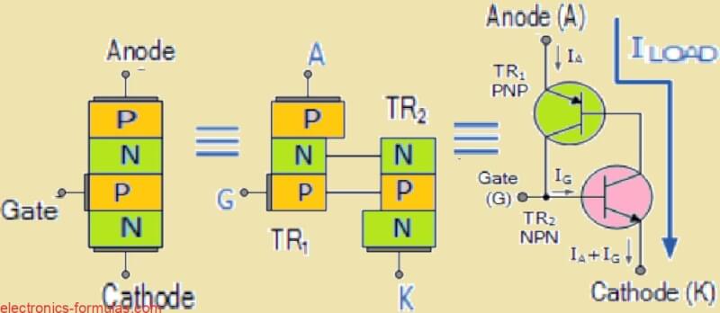
So now let us try to understand how this thyristor behaves internally by assuming that it is made using two transistors, one NPN and one PNP, joined in a special way. This is called two transistor equivalent model of the thyristor.
Now what happens is, the collector current of the NPN transistor (we call it TR2) goes directly into the base of the PNP transistor (called TR1). Same way, the collector current of TR1 feeds the base of TR2.
So both of these transistors are depending on each other. One will not work until the other one starts conducting. That means, they both get their base current only when the other one is already active.
So nothing will happen in the circuit unless we give some external current to the base of one transistor, usually TR2. Even if we give full voltage between Anode and Cathode, the device will still remain OFF until we give that small gate pulse.
What Happens When Anode is Negative
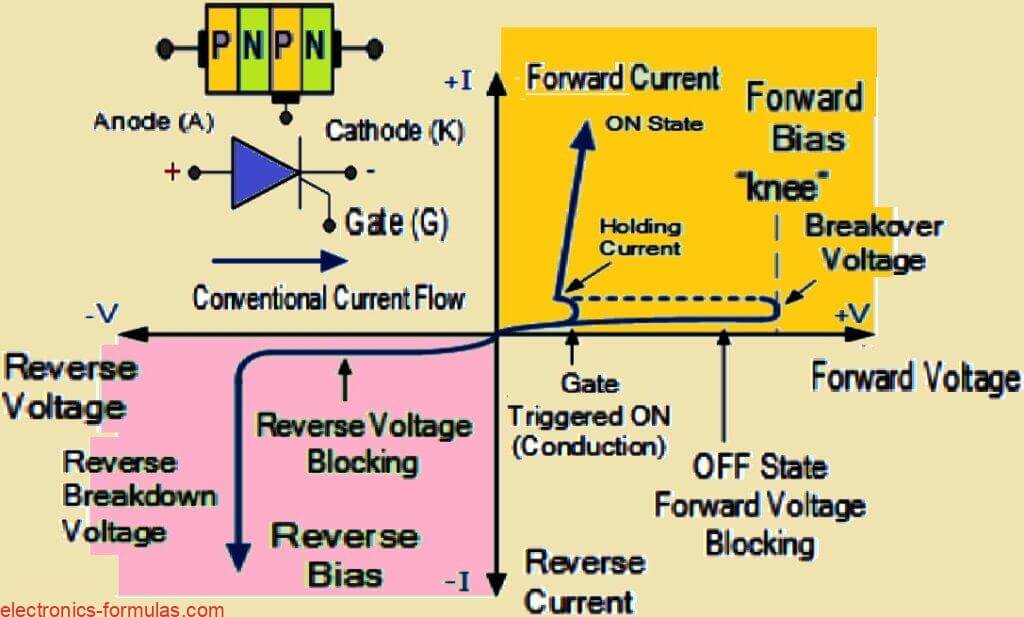
Now suppose we make the Anode side negative compared to the Cathode, that time what happens is, the middle N-P junction becomes forward biased, but the two outer P-N junctions become reverse biased. In this condition, the thyristor behaves just like a normal diode which is blocking the reverse current. No current can pass.
But if we keep increasing the reverse voltage too much, then at some point, the device may suddenly break down and start conducting even without any gate signal.
This is called reverse breakdown and it is dangerous. So this is one negative side of thyristors, sometimes they can turn ON by mistake due to reverse voltage spike, very high temperature or even due to a fast rising voltage pulse (what we call dv/dt).
What Happens When Anode is Positive
Now let us say we make the Anode side positive compared to the Cathode. In this case, the outer P-N junctions become forward biased, but the middle N-P junction becomes reverse biased. So again the thyristor will block the current and nothing happens.
But now if we give a small positive pulse to the base of NPN transistor TR2 then that base starts conducting and allows collector current to flow into TR1’s base. That activates the PNP transistor TR1 and that again gives more base current to TR2.
This thing goes on repeating and in just a tiny moment both transistors lock each other into full conduction mode. This is called regenerative feedback action, and it is very powerful, it cannot stop once it begins.
So finally the thyristor turns ON fully and now current can flow easily from Anode to Cathode. The resistance of the path becomes very low, less than 1 ohm, so very little voltage drop happens across the thyristor and that also means less power is wasted.
How a Thyristor Behaves in AC Circuit
So from all this, we can clearly understand that when the thyristor is OFF then it blocks the current in both directions of AC, just like an open switch. But when we give a small positive pulse at the gate terminal (which is actually base of transistor TR2), then thyristor turns ON and behaves just like a normal rectifier diode.
So finally we can say that this device is very powerful and very sensitive. It must be triggered carefully and once triggered, it will keep conducting until the external AC cycle or load current brings it back to zero.
The following images show the voltage-current I-V characteristics curves for the working of a Silicon Controlled Rectifier:
Why Gate Loses Control After SCR is Switched ON
So now once we give a gate pulse and the thyristor turns ON and current starts flowing from Anode to Cathode, that time the gate has no more control over the device. This happens because of that regenerative latching effect which we already discussed before, where the two internal transistors keep each other ON permanently.
Now if we try to give any more gate pulses after the thyristor is ON, then nothing will happen because now the device is already conducting and it is fully ON. The gate has lost all control.
Why SCR Cannot Work Like a Normal Transistor
We know that a normal transistor can be controlled by giving different base voltages, it can work in active region, saturation, or cutoff mode. But this is not the case with SCR or thyristor.
We cannot keep it in some intermediate conducting region. The SCR can either be completely OFF or completely ON, just like switch. Even the size or time duration of gate signal does not matter much, just a tiny momentary gate pulse is enough to turn ON the device. And once it is ON, then even if we remove the gate wire, it will still stay ON.
So we can say that this device behaves like a bistable latch, it has only two states, either OFF or ON. That is why it is very useful in circuits where we want to hold something ON without giving continuous signal.
How to Switch OFF a Thyristor or SCR
So now the question comes, how can we switch it OFF?
Once the SCR is ON and current is flowing from Anode to Cathode, then we cannot use the gate to switch it OFF. That method will not work. The only way to turn it OFF is by stopping the current flowing through Anode.
There are two main ways to do this:
- We remove the power supply or somehow disconnect the main input voltage so the current becomes zero.
- Or we create a way in the circuit where the Anode to Cathode current goes below a special value called “holding current” denoted by IH.
This holding current is the minimum amount of current required to keep the SCR ON. If current falls below this then the latching action stops and the thyristor turns OFF.
So we must make sure that the load current which is also Anode current (denoted by IL), is always more than IH to keep the SCR ON. That means:
IL > IH
Once it drops below that, then internal PN junctions come back to their blocking condition.
What Happens in AC Circuits: Natural Commutation
Now let us see what happens when the SCR is working in an AC circuit. We know that AC supply keeps reversing its polarity every half cycle from positive to negative and back.
So in AC, during each half cycle, the current automatically becomes zero at the center crossover point. That time the Anode current naturally drops to zero. So this means that the thyristor also automatically turns OFF. This is called natural commutation.
Because of this natural behavior, we do not need to create any special OFF method in AC circuits. The SCR will turn OFF on its own during every half cycle, especially at the 180-degree point which is the zero crossing of the sine wave.
Why Natural Commutation Does Not Happen in DC Circuits
But if we use this SCR in a DC circuit then the supply voltage is continuous, it does not reverse like AC. So the current will never become zero on its own.
That means natural commutation cannot happen in DC. In that case, we must create some extra method in the circuit to make the SCR OFF at the required time, like opening a switch or using another device to break the current.
How Gate Pulse Triggers SCR in AC and Enables Phase Control
Now let us again look at AC behavior in detail.
During the positive half cycle of AC, the Anode becomes positive and SCR becomes forward biased. If we give the gate pulse at this moment, then SCR will turn ON and conduct current.
But when the negative half cycle comes then Anode becomes negative and the SCR becomes reverse biased, so it will not conduct, even if we give gate signal at that time. So we should give gate pulse only during the positive half.
This thing gives us a powerful control method called phase control. That means that we can decide exactly when to trigger the SCR during the positive cycle, either early or late, and by doing this, we can control how much power we are delivering to the load.
This is why SCR is so useful in AC power control circuits, like light dimmers, fan speed controllers, motor control and other similar systems.
Phase Control in Thyristors
How SCR Controls Power During AC Positive Cycle
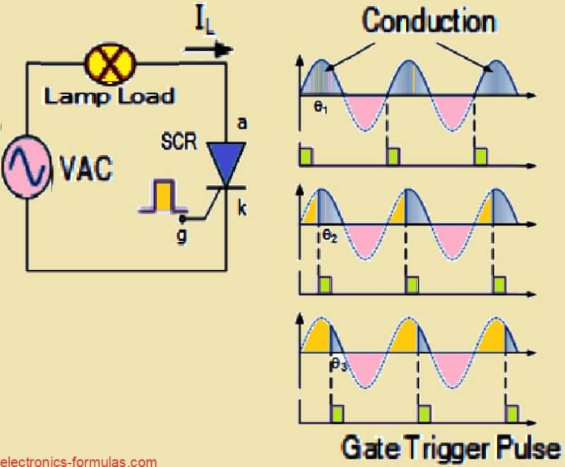
So now what happens is, at the very beginning of every positive half-cycle of the AC waveform, the SCR is totally OFF. It will not conduct anything until we apply the gate pulse.
Once we give a gate trigger, then SCR becomes ON and then it stays fully latched ON for the rest of that positive half-cycle. It does not need the gate anymore during that cycle.
Now suppose we give this gate signal exactly at 0 degree, that is the very start of the cycle then the SCR will remain ON throughout the full positive waveform. That means the load, like a lamp or heater, will receive full half-wave AC and the average voltage will be around:
0.318 × Vp
Here Vp is the peak voltage of the AC.
So in this condition, the load gets maximum brightness or maximum heating effect.
What Happens if We Delay the Trigger
But now if we delay the gate signal, and give it later in the half-cycle, like at 30° or 60° or even 90° then the SCR will remain OFF for some time, and only turn ON after the gate is applied.
This means the lamp or heater will get power for a shorter duration and the average voltage given to the load will also become less. So brightness will reduce.
As we increase this delay (i.e., phase angle θ from 0° to 90°), the ON time becomes shorter and load gets less and less power.
SCR Can Work Like a Light Dimmer or AC Power Controller
So now we can understand, this simple behavior gives us a nice method to use SCR as a dimmer. We can use it to control the brightness of a lamp by just controlling the gate pulse timing.
In the same way, we can use it to control speed of an AC motor, or temperature of a heater, or voltage delivered to any AC-powered equipment.
This method is called phase control, and it is one of the most common uses of SCR in AC systems.
Why SCR Only Works in Half-Wave Mode
Until now we saw that SCR works only when Anode is positive, that is, only in the positive half-cycle of AC.
During the negative half-cycle, the Anode becomes negative and the SCR becomes reverse biased and it will block the current no matter what gate signal we give. So it acts just like a diode, it will not conduct in reverse.
So we say that a normal SCR is a half-wave device, it only conducts in one direction, during the positive half of the AC waveform.
Other Thyristor Devices for Full-Wave or Gate-OFF Control
But now, engineers have created more advanced thyristor-type devices that can do more things than a normal SCR.
These special devices can either:
- Conduct both directions (full-wave),
- Or be turned OFF using the gate (which a normal SCR cannot do),
- Or be triggered using light.
Some of these advanced thyristor family devices are:
- GTO – Gate Turn-Off Thyristor
- SITH – Static Induction Thyristor
- MCT – MOS Controlled Thyristor
- SCS – Silicon Controlled Switch
- TRIAC – Triode Thyristor (can conduct both ways)
- LASCR – Light Activated SCR
All these devices are available in many voltage and current ratings, and they are used in very high power control systems like industrial motors, heaters, welding systems and so on.
Conclusions
So here we are talking about Silicon Controlled Rectifiers that we normally call as Thyristors. These are special types of semiconductor devices which are made using three junctions and total four layers like PNPN structure. We can also think of them like two transistors which are internally joined with each other in a special feedback way. That is why they are mostly used in switching heavy electrical loads like motors, lamps, heaters etc.
Now these thyristors do not need continuous signal on gate. Just one small positive pulse at the Gate pin is enough to turn the thyristor ON and once it turns ON, it will keep passing current even if we remove that gate pulse completely. It will stay ON permanently until the current flowing from Anode to Cathode goes below a certain very small level which we call as minimum latching current. So that is how it works in simple way.
Simple Static Features of a Thyristor
So now let us look at what are the basic simple characteristics or features of a thyristor device. Right, so here are the points.
First thing is that this thyristor cannot work in analog or linear mode. It only works like a switch. So it is either totally ON or totally OFF.
Then next, this is a current controlled device. That means that we use a very small current at the Gate pin to control a much bigger current flowing from Anode to Cathode side.
But that current will flow only when we apply a forward voltage across Anode and Cathode and also apply that triggering current on the Gate. Without both conditions together, it will not turn ON.
Now once it turns ON, the thyristor will start behaving just like a diode and will allow current to pass without resistance.
To keep this ON condition active, the Anode current must be always more than the holding current level. If the Anode current falls below that holding level, then it will automatically turn OFF.
If we apply reverse voltage across Anode and Cathode then it blocks the current completely, even if we keep applying signal at the Gate. So in reverse direction it always blocks current.
Now here is one more important point. Once it is turned ON using that small Gate current, then even if we remove the Gate signal, it will continue to stay ON as long as the Anode current is above the minimum level. This is because of the special feedback design inside its layers which keeps it latched.
So because of this fast ON OFF capability and no moving parts inside, thyristors are much better than old mechanical type relays. They do not suffer from dust, corrosion, spark or wear and tear.
And apart from just simple ON OFF switching, we can also use thyristors to control average power going to a load like in dimmers, fan regulators, heater control and so on. Because in AC supply we can trigger it at any point of the waveform to adjust the power reaching the output.
So in short this thyristor is a very useful high power semiconductor switch that can be used in many different types of AC and DC control circuits.
Sources:
Leave a Reply