Basically passive RC filters are circuits that separate various frequencies within a signal. We can consider a signal as a collection of distinct-pitched noises. We can make an RC filter to only allow high-pitched sounds to pass through (such as a treble filter) or only the low-pitched sounds to pass through (similar to a bass filter in a speaker).
Resistors, which regulate current, and capacitors, which temporarily store electrical energy, are commonly used in the construction of these filters.
For low frequency applications they are easy to employ (up to around 100 kHz), however, for higher frequencies, inductors (which store energy in a magnetic field) are frequently employed instead of capacitors.
Contrary to filters that employ transistors, these filters are incapable of increasing the signal intensity because they only incorporate resistors, capacitors, and inductors. Thus, there will always be a signal difference between the input and output.
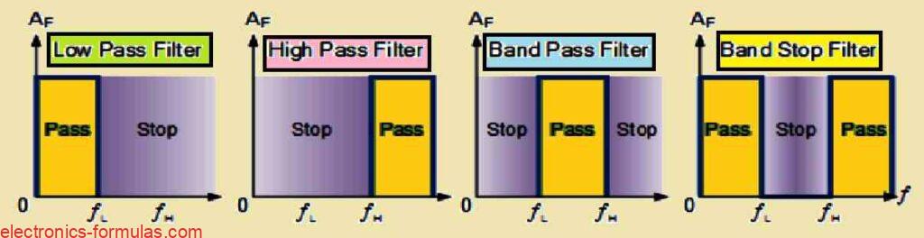
Filters are categorized according to the frequencies they allow to pass through.
Common ones include low-pass filters (like the bass filter example above) high-pass filters (treble filters), and band-pass filters (which allow through a specified range of frequencies in the middle),.
Low Pass Filter: Consider a sound system that has a bass knob. A low pass filter functions similarly to that knob. It allows all low-pitched noises (from 0 Hz) up to a specified frequency, known as the fc (cut-off frequency), while blocking any higher-pitched sounds above that point.
High Pass Filter: This filter is the opposite of the low-pass filter. Imagine a treble knob on a speaker. A high pass filter allows all high-pitched noises above a certain frequency (cut-off frequency), while blocking all lower-pitched sounds below that point.
Band Pass Filter: This filter is somewhat more selective. It is similar to selecting a particular radio channel in your radio. It only makes it possible frequencies in a specific range to pass through, which is specified by two cut-off points: the lower cut-off frequency and the higher cut-off frequency. Everything beyond this range is blocked.
Making Simple Filters with Capacitors and Resistors
Resistors and capacitors are two basic electrical components that may be used to create simple filters. First-order passive filters often known as 1st order filters, are so named because they exhibit a straightforward response to various frequencies and only need one of each component.
It Matters How the Circuit Is Set Up
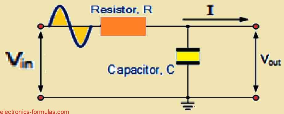
The filter functions as a low-pass or high-pass filter depending on how the resistor and capacitor are connected. After applying the input signal (VIN) across the resistor and capacitor, the output (VOUT) can be obtained from their connecting point.
Filters: Organizing Wavelengths
A filter’s function is to minimize the strength of some frequencies while allowing others to pass through on a selective basis.
While real-world filters reduce or decrease undesirable frequencies, ideal filters would completely eliminate them.
A frequency response curve can be used to depict a filter’s response, or how it affects various frequencies.
Each of the four fundamental categories of filters has a unique characteristic curve.
Next, we will go further into these categories.
Response Curves of ideal Filters
Active and passive filters fall into these two main categories. To increase the signal intensity, active filters employ special components like transistors. In contrast, the output signal of passive filters is always weaker than the input because these devices do not have transistor amplifiers.
This is so because they can’t produce a stronger signal since they rely on inductors, resistors, and capacitors to adjust frequencies. Thus, with a strength of less than 1 (unity), passive RC filters attenuate or weaken the signal.
Understanding Low-Pass Filters
Low-pass filters are designed to allow low-frequency signals to pass through but prevent high-frequency ones. Capacitors, resistors, inductors, or a mix of these can be used to build them.
The important thing to remember is that this transition occurs at a certain frequency known as the cut-off frequency. Frequencies beyond the cut-off point are substantially cut down, while those below experience very little or no weakening
Easy vs. Hard Low-Pass Filters
A single resistor and capacitor are all that are needed for the most basic kind of low-pass filter (RC filter). In this tutorial, we’ll be concentrating on this. On the other hand, combinations of parallel-connected capacitors and series-connected inductors can be used to create more complex low-pass filters.
How to Make a Simple Low-Pass Filter
You may find it quite simple to construct the most basic kind of low-pass filter which is often known as a passive RC low-pass filter (LPF). There are just two things needed:
Resistor (R): This part regulates the circuit’s current flow.
Capacitor (C): This part functions as a temporary electrical energy storage device.
These two parts are positioned in a line with the input signal (VIN) passing through both of them since they have been connected in series. But notice that, only the signal across the capacitor is used to obtain the output (VOUT).
The Reason Behind the Name “First-Order Filter”
The capacitor is the sole reactive part used in this simple low-pass filter, earning it the moniker “first-order filter” or “one-pole filter.” Recall that capacitors and inductors are examples of reactive components, they affect how the circuit reacts to various frequencies.
Because here we have only a single working capacitor, the “one-pole” moniker refers to this specific location in the filter’s behavior where there is a large frequency change.
Low Pass Filter Circuit using a Single Resistor and a Capacitor
How Capacitor Affects Frequeyncy
As we previously discussed, the frequency of the signal affects a capacitor’s reactance, or its capacity to oppose current flow. A capacitor’s reactance becomes less as the frequency increases, unlike a resistor, whose resistance remains constant. This is the fundamental working principle of the RC low-pass filter.
Capacitor Advantage at Low Frequencies
In comparison to the resistor’s resistance, the capacitor’s reactance is extremely high at low frequencies. This indicates that because the capacitor (VC) provides a much higher opposition to the current flow, a significant portion of the signal voltage (VIN) drops across it. On the other hand, there is a significantly lower voltage drop across the resistor (VR).
High Frequencies Favor the Resistor
The reactance of the capacitor decreases with increasing frequency. This lowers the voltage drop across it by allowing more current to pass through it (VC). On the other hand, when the resistor (VR) experiences a lesser opposition from the capacitor, the voltage drop across it rises.
Filter as a variable voltage divider
Consider this circuit to be a frequency-controlled voltage divider.
Remember how we used a formula to get the output voltage of a circuit with two resistors connected in series?
In this RC filter, the capacitor functions as a frequency-dependent resistor, determining how much voltage is shared between it (VC) and the resistor (VR).
At low frequencies, the capacitor absorbs a greater portion of the voltage but at high frequencies, the resistor dominates.
This tendency allows the filter to more readily pass low frequencies while attenuating high frequencies.
Although the circuit shown above is for an RC Low Pass Filter, it may also be considered a frequency-dependent variable potential divider circuit, much like the one we studied in the Resistors lesson. When calculating the output voltage of two single resistors linked in series, we employed the following formula in that lesson.
VOUT = Vin * [R2 / (R1 + R2)]
In this formula, the R1 + R2 = RT represents the total resistance of the circuit.
We are also aware that the capacitive reactance of a capacitor in an AC circuit can be calculated as:
XC = 1 / 2πfC (in Ohms)
The term “impedance,” which has the symbol Z, represents the opposition to current flow in an AC circuit. The circuit impedance for a series circuit made up of a single resistor and a single capacitor can be calculated as follows:
Z = √(R2 + XC2 )
RC Potential Divider Equation
Next, we may obtain the following by substituting the resistive potential divider equation with our equation for impedance from above:
VOUT = Vin * {XC / [√(R2 + XC2 )]} = Vin(XC / Z)
This means that we can get the output voltage of an RC filter for a specific frequency by utilizing the potential divider equation of two resistors in series and substituting for impedance.
Solving a Low Pass Filter Problem#1
Let us now analyze a simple RC low-pass filter circuit. The circuit consists of a resistor (R) with a value of 2.2 kΩ connected in series with a capacitor (C) with a capacitance of 22 nF. This circuit is connected across a 6 V AC power supply. We want to calculate the output voltage (VOUT) at two different frequencies: 100 Hz and 10 kHz.
Calculating Output Voltage at a Frequency of 100 Hz.
XC (100 Hz) = 1 / (2 * π * 100 Hz * 22 x 10-9 F) = 72343.156 ohms
VOUT = VIN[XC / √R2 + (XC)2] = 6 * [72343 / (√(22002 + 723432)] = 5.99 V
Now Let’s Voltage Output at a Frequency of 10,000Hz (10kHz)
XC (100000 Hz) = 1 / (2 * π * 10000 Hz * 22 x 10-9 F) = 723.43 ohms
VOUT = VIN[XC / √R2 + (XC)2] = 6 * [723.43 / (√(2200^2 + 723.43^2)] = 1.87 V
Frequency Response
We can see an intriguing pattern from the above data. The output voltage, or VOUT, drops as the frequency of the signal sent into the RC network increases due to a decrease in the voltage across the capacitor. More specifically, we see a decrease in output voltage from 5.99 volts to 1.87 volts when we increase the frequency from 100Hz to 10kHz.
A graphic representation of the circuit’s frequency response may be constructed by plotting this relationship between the output voltage and various input frequencies.
This graphical representation is known as a frequency response curve or a bode plot. Below is a plot of our low-pass filter circuit.
Frequency Response of a 1st-order Low Pass Filter
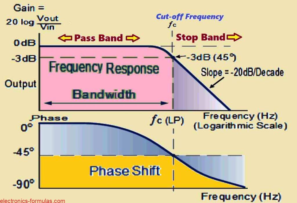
Utilizing the Bode Plot to Interpret the Filter’s Behavior
The frequency response of the filter is shown by the Bode Plot. Low frequencies give the plot an almost flat appearance.
This shows that almost all of the input signal flows through the filter without being altered, giving rise to a gain that is almost equal to 1 (unity gain).
The reason for this behavior is that the capacitor effectively blocks current flow at low frequencies due to its high reactance.
But the circuit’s responsiveness starts declining as the frequency increases and approaches the cut-off frequency (fc).
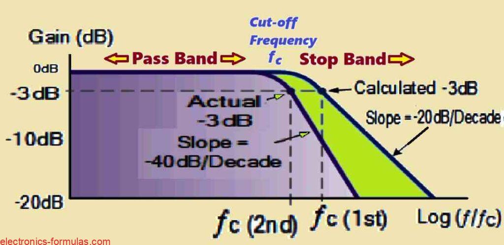
The graph indicates a roll-off beyond this point at a rate of -20 dB per decade (-6 dB per octave).
That being said, please note that every RC circuit will have this particular roll-off slope of -20 dB/decade, regardless of the what resistor and capacitor values are selected.
Why High Frequencies Are Blocked by the Filter
Any signals that have frequencies higher than the cut-off point will be significantly attenuated, which means that they will be much weaker. This occurs because the reactance of the capacitor gets extremely low at high frequencies.
To put it another way, the input and output begin to function as a direct connection (short circuit) when the capacitor is present. The consequence is an output voltage that is almost zero since the signal hardly makes it to the output.
A variety of low frequencies can be allowed to pass through an RC circuit without causing any problems provided the resistor and capacitor values are appropriately selected.
On the other hand, signals that have frequencies higher than the specified cut-off point will be blocked or muted. This results in what we term a low-pass filter.
Understanding the Passband and Stopband of the Low-Pass Filter
A low-pass filter circuit operates according to a certain key frequencies:
Passband: All frequencies below the cut-off frequency (fc) are included in this zone. This band of signals has little to no attenuation, which means that they pass through the filter with little to no weakening. This range also serves as a representation of the filter’s bandwidth, or the range of frequencies it permits to flow through.
Stopband: All frequencies above the cut-off frequency fall within this zone. The filter effectively weakens, or greatly attenuates, signals in this band.
The cut-off frequency is a crucial frequency at which the reactance and resistance of the capacitor equalize (R = Xc).
The output signal at this particular frequency is attenuated to around 70.7% of the original input signal, or -3 dB (20 log (Vout/Vin)) in decibels (dB).
It is important to observe that the output is not precisely half of the input, even if the resistance and reactance are equal at the cut-off frequency. This is due to the fact that the voltage components add vectorially, producing an output that is 0.707 times the input.
The Lag Effect of the Capacitor and Phase Shift
A phase lag (Φ) between the input and output signals is caused by the presence of a capacitor in the low-pass filter. This indicates that the output voltage (VOUT) across the capacitor peaks somewhat later than the input voltage (VIN).
This phase lag is -45° at the -3 dB cut-off frequency (fc), when the signal’s strength is attenuated.
This lag is caused by the capacitors slow rate of charging and discharging when the input voltage fluctuates.
Consequently, the output voltage which is the voltage across the capacitor, lags behind the variations in the input voltage.
Moreover the capacitor’s effective capacity to charge and discharge decreases with increasing input signal frequency. This results in a more noticeable lag which moves the output signal more out of phase with the input signal.
Calculating the Cut-off Frequency and Phase Shift
Referring to our previous low pass filter problem#1, the following formula may be used to determine the phase shift angle and the cut-off frequency point:
fc = 1 / (2 * π * R * C) = 1 / (2 * π * 2200 * 22 * 10-9) = 3288.32 Hz
Phase Shift Φ = -arctan (2πfR C)
Thus, as the phase shift angle is -45 degrees, the output voltage is 70.7% of the input voltage value, and the cut-off frequency (fc) is 3288.32 Hz for the basic “Low Pass Filter” problem#1.
Second-order Low Pass Filter
According to our analysis, a single resistor (R) and a single capacitor (C) may be connected in series to create a simple first-order RC low-pass filter.
A roll-off slope of -20 dB/decade is offered by this single-pole arrangement at frequencies higher than the cut-off point (f-3dB).
This -20 dB/decade (-6 dB/octave) slope, however, might not be effective to sufficiently attenuate unwanted signals in some filter applications.
In these situations cascading multiple filter stages allows us to obtain a deeper attenuation characteristic.
Basically this refers to connecting two or more separate RC low-pass filters in series. The cascading arrangement provides a cumulative roll-off slope that is higher than the slopes of the individual filter stages.
This method makes it possible, to eliminate undesired high-frequency components from the signal more successfully.
Diagram for Second-order Low Pass Filter
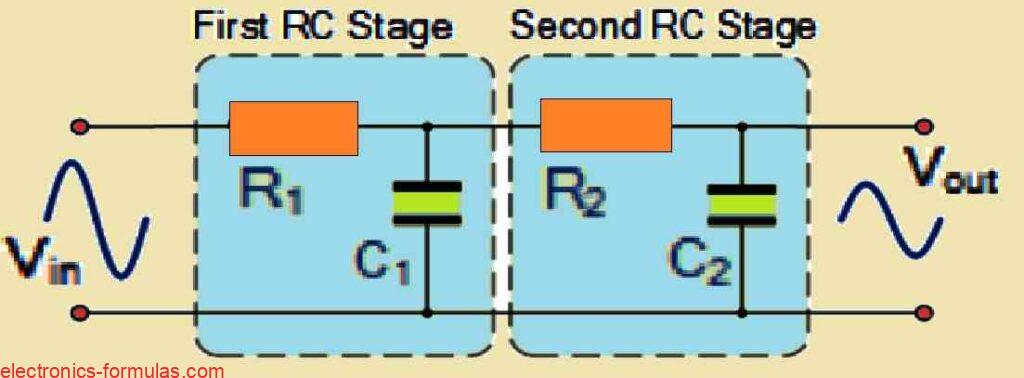
The above shown , the circuit makes use of two passive, first-order low-pass filters that are connected in series, or “cascaded.” With this setup, a two-pole or second-order filter network can be developed.
This illustrates how a simple first-order low-pass filter can be converted to a second-order kind by simply adding another RC network to it. Furthermore, the number of RC stages cascaded determines the order of the resultant filter.
If we cascade a sequence of n RC stages, the resulting RC filter is called a “nth-order” filter. This filter has a roll-off slope of “n x -20 dB/decade.” For example a second-order filter gets a steeper slope of -40 dB/decade (-12 dB/octave) and a fourth-order filter gets an even steeper slope of -80 dB/decade (-24 dB/octave).
This tendency continues as the filter order increases. This simply means that increasing the filter order results in an increased roll-off slope. This also means that the filter’s stopband response approaches its ideal characteristics more closely.
The Importance and Limitations of Cascaded Filters
Second-order filters are very important and widely used in filter design. When used in conjunction with first-order filters, they function as the foundation for any higher-order (nth-order) filter. For example, a third-order low-pass filter may be built by cascading a first- and second-order low-pass filter in sequence.
But you may find a trade-off while cascading RC filter stages. Although there is no hypothetical restriction to the number of possible filter orders, increasing the order might result in a decrease in the final gain of the filter and accuracy.
The cascading of similar RC filter stages allows you to reduce the output gain at the specified cut-off frequency. This attenuation is proportional to the number of cascaded steps, which corresponds to the steeper roll-off slope attained. The following formula could be used to calculate the level of attenuation at the desired cut-off frequency:
(1 / √2)n
Cascading causes gain attenuation at the cut-off frequency.
The above formula describes the relationship between the number of cascaded filter stages (n) and the gain attenuation at the cut-off frequency (fc) for passive low-pass filters.
Below is an overview of the formula and its ramifications:
n: This is the total number of filter stages in the cascaded filter network.
Gain Attenuation: When the total amount of stages (n) increases, the gain at the cut-off frequency (fc) drops gradually.
This attenuation can be expressed as a factor of the original voltage (Vin).
Example of Gain Attenuation with Cascading
Second-Order Filter (n = 2): In this example, the gain at fc is lowered to 0.7071 * 0.7071 of the original voltage (Vin), resulting in about 0.5Vin or -6 dB (decibels) in relation to the input.
Third-Order Filter (n = 3): The gain at fc decreases further to 0.353Vin, or approximately -9 dB.
Fourth-Order Filter (n = 4): The gain at fc is reduced more significantly to 0.25Vin, or around -12 dB.
Cut-Off Frequency of Second-Order Filters
fc = 1 / 2π√(R1C1 * R2C2) (in Hz)
In the real world, cascading more filter stages increases the total roll-off slope of the filter network. But this has an impact on the low-pass filter’s performance.
Cut-Off Frequency Shift: The previously estimated -3dB corner frequency point (fc) of the particular filter stage changes somewhat higher in frequency.
This indicates that the filter’s crossover from the passband to the stopband happens at a higher frequency than anticipated.
Passband Modification: Because of the shifted cut-off frequency, the filter’s passband (the range of frequencies which travel across unaffected) becomes somewhat narrower.
The result is that a narrower range of frequencies is going to experience less attenuation, than the the original single-stage filter.
The equation below calculates the change in cut-off frequency depending on the total number of cascaded stages (n).
Low Pass Filter, 2nd Order, -3dB Frequency
f(-3dB) = fc √(2(1/n) – 1)
In the above formula fc is the estimated cut-off frequency, n is the filter order, and ̒-3dB is the new pass band frequency of -3dB because of the filter order being increased.
A Second-order Low Pass Filter’s Frequency Response
If a second-order low pass filter were to have an identical -3dB cut-off point, the frequency response (bode plot) would subsequently resemble this:
Although cascading passive filters provide a way to construct higher-order filters, correct implementation of this approach can be practically challenging. This challenge results from each filter stage’s dynamic impedance interacting with and affecting the impedance of its adjacent network. As a result the desired filter response may not be achieved.
One popular technique to counteract this “loading effect” is, to adjust the impedance of each successive step. To do this the impedance of stage 2 (the next step) must be 10 times higher than that of stage 1 (the previous stage). You can implement this by setting the resistor value (R2) of stage 2 to 10 times that of stage 1’s resistor value (R1). On the other hand the stage 2’s capacitor value (C2) would need to be one-tenth that of stage 1’s capacitance (C1) (C2 = 1/10th C1) and so on.
It is crucial to remember that operational amplifier (op-amp) feedback circuits often use second-order and higher-order filter networks. We then refer to these filters as “active filters.” As an alternative these could be employed in circuits that incorporate RC oscillators as phase-shift networks.
Conclusions (Low Pass Filter Recap)
In conclusion we can say that the Low Pass Filter acts like a frequency gatekeeper, since it lets through a steady stream of voltage (DC) all the way up to a specific limit termed as the cut-off frequency (fc).
This cut-off point allows only a slightly weakened signal (down by 3dB or 0.707 times the original voltage) to pass through. Frequencies below fc are considered the “pass band” simply because they are allowed to pass through.
Anything that may be above fc gets blocked, and hence the name “stop band.” Building a basic low pass filter is quite simple, because all you need is one resistor and one capacitor connected in a specific way.
We can calculate the cut-off frequency by using an easy formula fc = 1 / (2πRC).
Interestingly you will find that at the cut-off point, the output signal experiences a phase shift of -45-degree.
In order to measure a filter’s effectiveness we use a unit called decibels (dB), which basically compares the output voltage with the input voltage, using a logarithmic scale.
The higher the dB value the stronger the signal.
To calculate gain in dB you can use the formula:
Gain (dB) = 20 log (Vout / Vin).
Passive low pass filters may be thought of as volume control knobs for audio frequencies. They dial down the level on high-pitched sounds and static, such as background talk during a party. This guarantees that low-frequency bass sounds are heard clearly and loudly, making them ideal for use with large bass speakers. When employed in this manner, these filters are referred to as “high-cut” or “treble cut.”
It’s similar like turning on a switch. If we change the positioning of the resistor and capacitor in the circuit, the filter begins to prefer high frequencies. This is the same as increasing the treble while decreasing the bass. In the forthcoming lesson, we’ll take a look at how this functions in the form of a high-pass filter.
In the above discussion we have concentrated on how low-pass filters behave in the frequency domain when they are stimulated by sinusoidal signals.
We subsequently found that the cutoff frequency of the filter, represented by fc, is directly proportional to the circuit’s product of capacitance (C) and resistance (R).
If we change R or C, the cutoff frequency (fc) will also change, meaning its value will either go higher or down. Additionally, there is a phase lag between the input and output signals as a result of the combination of R and C.
This lag results from the capacitor’s repetitive charging and discharging characteristics as the sine wave varies. Let us now go further into the idea of the circuit’s time constant (τ).
This parameter results from the interaction between R and C and originally appeared in RC circuit tutorials. The response of the filter in the time domain is controlled by the time constant.
It is related to the cutoff frequency using the equation below:
τ = RC = (1 / (2πfc)
This formula emphasizes the vital relationship between the attenuation of high frequencies by the filter and its time constant.
Put otherwise, a lower cutoff frequency is associated with a bigger time constant which may be obtained by increasing either R or C. This indicates that the input signal’s high frequency components have been more severely attenuated.
The above formula can be also expressed in terms of the cut-off frequency, ƒc as given below:
fc = 1 / (2πRC) or 1 / 2πτ
As we have seen the frequency of the input signal and the time constant of the circuit (τ) both affect the output voltage (VOUT). As previously determined, the circuit operates as a straightforward first-order low-pass filter with a sinusoidal input that changes progressively over time.
But, what would happen if we drastically changed the input signal? Let us say we swapped out the sinusoidal signal with a square wave signal, which is a kind of “ON/OFF” signal that has a step change that is almost vertical. This significant change in the input signal completely modifies the behavior of the circuit. The circuit in this case essentially transforms into an integrator, a distinct kind of filter.
Circuit design of an RC Integrator
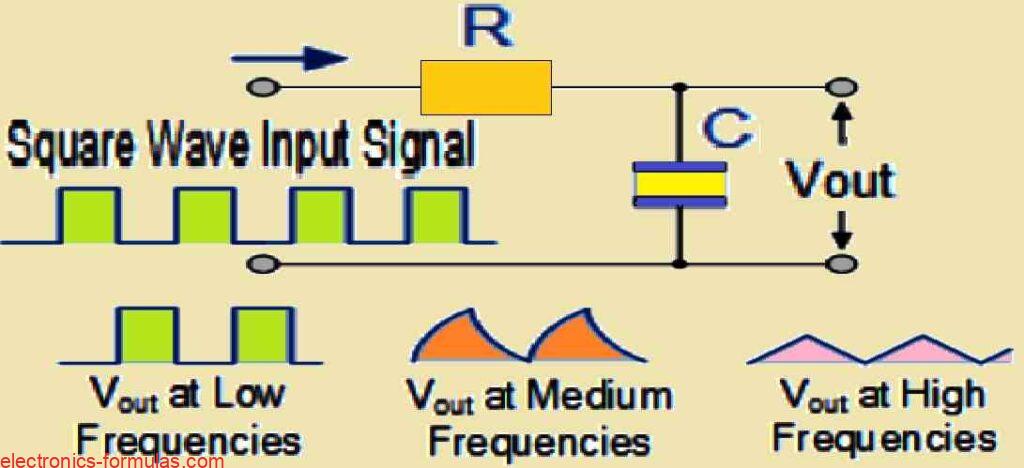
One particular kind of circuit that was developed from the low-pass filter is the RC Integrator. The integrator converts a square wave input signal with a “step” response—imagine a switch being rapidly turned on and off—into a triangle waveform output while operating in the time space. This transformation happens because the circuit’s capacitor charges and discharges in response to the sudden alterations in the input signal.
A triangle waveform is distinguished by its alternating positive and negative ramps which have equal duration and amplitude. The most important point is this: The RC time constant (τ) becomes an important factor for shaping the output waveform. The resultant output will have the shape of an ideal triangle wave if the time constant is much longer than the period of the input square wave.
Additionally an increased input frequency results in a smaller output amplitude than the input. This occurs as a result of shorter charge or discharge times of the capacitor at higher frequencies, which reduces the output waveform’s voltage swing.
This distinctive characteristics of the RC integrator makes it ideal for applications, that need the conversion of one form of electrical signal to another. Because of its capacity to convert a square wave into a triangular waveform, the integrator is an important tool in wave-generating circuits. Furthermore its ability to change the shape of waveforms makes it an effective component in wave-shaping circuits. These circuits are used in many electrical systems to modify signals for specialized objectives.
References: Low Pass Filter
Leave a Reply