In digital logic circuits, a “Logic OR Gate” functions depending on the specific conditions we apply to its input to produce its output which is written as Q. We get a LOW output from an OR gate only when all of its inputs are applied with a LOW state (logic level “0”), and if any […]
Understanding the Logic AND Gate: A Comprehensive Guide
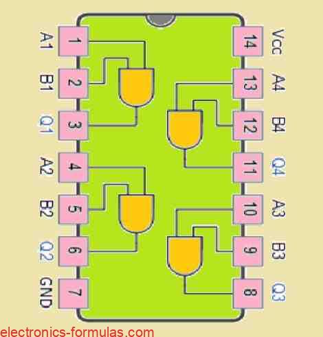
A digital logic AND gate is a type of circuit that produces an output based on its two inputs. For an AND gate you will find that its output is only “HIGH” (which means true or 1) whenever both of its inputs are “HIGH” (true or 1). If we turn either of inputs “LOW” (false […]
Understanding Digital Logic Gates: From Basic Functions to Advanced IC Classifications
Normally you will find a digital logic gate will accept multiple inputs, for example A, B, C, D, etc., but would mostly provide only one digital output, denoted as Q. We can connect or cascade multiple individual logic gates, to generate logic gate functions with any desired number of inputs, which can be used to […]
Sallen-Key Filter Circuit: A Building Block for Filters
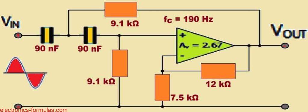
Throughout my electronics career I have found the Sallen-Key filter to be an excellent tool in my circuit design toolset. It is an active filter… which means it shapes the signal using devices such as op amps. What makes it so attractive is actually its simplicity and adaptability. How Does It Work? A Sallen-Key filter […]
Decibel Calculations: From Basics to Advanced Applications
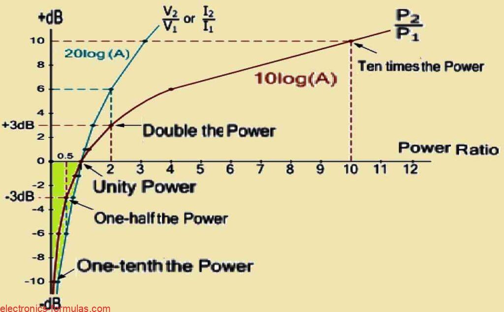
We usually think of decibels as being used to measure loudness. But when designing amplifier and filter circuit layouts, we typically come across numerical values that have extremely wide ranges. For example, a total gain of 665 (19 multiplied by 35) is obtained through cascading two amplifier stages with power gains of 19 and 35 […]
Band Stop Filter Circuit: Explained with Formulas
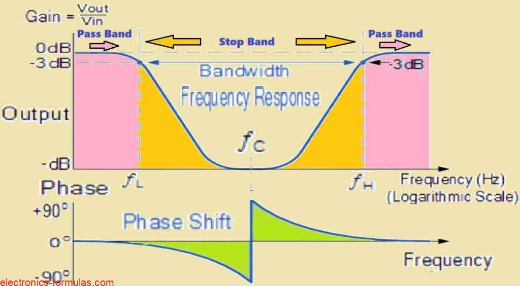
Another name for a band Stop Filter is the Notch Filter, which is designed to block and reject all frequencies that fall between its two cut-off frequency points, however all frequencies that are on the outer sides of this range, are allowed to pass through. A straightforward band-pass filter is created when we combine a simple […]