
Ok, in this post I will teach you regarding Class-B amplifiers and how it works. So if we want to make the full power efficiency of that old Class A amplifier a whole lot better by cutting down on the power that just gets wasted as heat, we can totally redesign the power amplifier circuit. […]
Class-A Amplifier Working Explained using Formulas
The common emitter class-A amplifier is specifically engineered to generate a significant output voltage swing even when it is fed with a relatively minuscule input signal voltage that might only be a few millivolts. These amplifiers are primarily utilized as what we call “small signal amplifiers” a concept we explored in our earlier tutorials. Now […]
Understanding Distortion in Amplifier Circuits
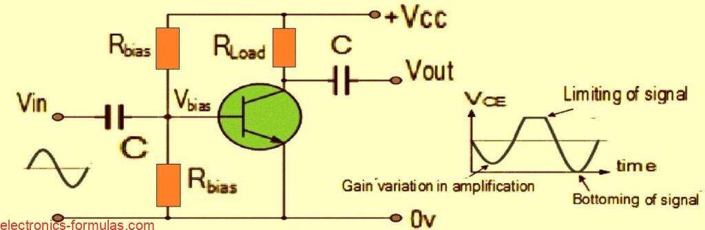
In order for a signal amplifier to do its job properly and make sure that the output signal does not get distorted in any way it is really important to have some kind of DC Bias applied to its Base or Gate terminal. You see, a DC bias is necessary because it allows the amplifier […]
Understanding Common Source JFET Amplifier Circuit
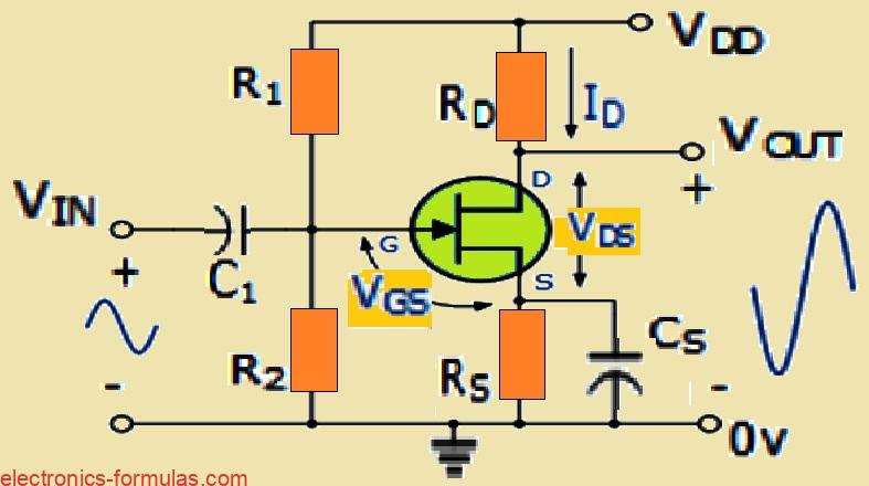
When we talk about the common source JFET amplifier, there is this really cool advantage that it has over the common-emitter BJT amplifier. The big deal here is that the Field Effect Transistor or FET for short, boasts an incredibly high input impedance. This means it can handle very tiny input voltage signals without breaking […]
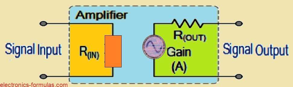
Common Emitter Amplifier Circuit: Explained with Formulas

Basically when we talk about transistor amplifiers, they are designed to work with AC input signals that goes up and down between a positive value and a negative values. Now to make sure that the transistor can work properly between these two extreme points, we need to set things up in a specific way. This […]
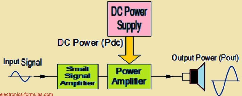
Audio Amplifier Basics Explained
We often use term “amplifier” to refer to a circuit that takes input signal and produces an amplified version of it. But as we go deeper into amplifier tutorial, we will discover that not all amplifier circuits are created equal, they are categorized based on their circuit configurations and modes of operation. In electronics we […]