
When we talk about charging a capacitor it is not something that can happen instantly. This is because capacitors have specific current-voltage i-v characteristics that shift depending on time.
If you connect a resistor R and a capacitor C together into a circuit, you will get what is called an RC charging circuit.
This setup has a behavior that changes over time in an exponential way, meaning the rate at which things happen starts off fast, but then slows down gradually.
In fact, every single electrical or electronic circuit out there deals with some level of time-delay, when you apply a signal or voltage whether it is DC or AC and when the circuit responds to it.
This delay is called the circuit’s time delay or Time Constant. Think of this time constant as the speed at which a circuit reacts when you introduce an input signal or voltage at it.
The size of this time constant depends mostly on the reactive components like the capacitors or the inductors that are being used in the circuit. The time constant is measured in something called Tau or T.
So let us say you have got a capacitor that has not been charged yet and you suddenly apply a DC voltage to it.
The capacitor starts to draw something called a charging current and begins to store energy, this is what we call charging up.
Then if you lower the voltage the capacitor does the opposite, it releases that stored energy and discharges. You can kind of think of capacitors like small batteries, they store electrical energy and then release it when needed.
The amount of electrical charge that gets stored on the plates of the capacitor can be calculated using the formula Q = CV, where Q is the charge C is the capacitance and V is the voltage.
Now this charging and discharging process is not instant, it takes a little bit of time to get done. The amount of time it takes for a capacitor to charge up or discharge to a certain level of its maximum capacity is what we call its Time Constant T.
Now if you connect a resistor in series with the capacitor creating an RC circuit, the charging process becomes more gradual.
The capacitor will slowly charge up through the resistor until the voltage across the capacitor equals the supply voltage. It takes about 5 time constants or 5T for the capacitor to fully charge.
So when we talk about the transient response of an RC circuit, we are basically saying that it takes 5 time constants for things to settle down.
The time T or transient response time is calculated using the formula T = R * C, where R is the resistance in ohms and C is the capacitance in farads.
Essentially, that is the backbone of any RC charging circuit, 5T just means 5 times RC (5 * RC), and that is exactly how long it takes for any capacitor to get fully charged.
Analyzing an RC Charging Circuit

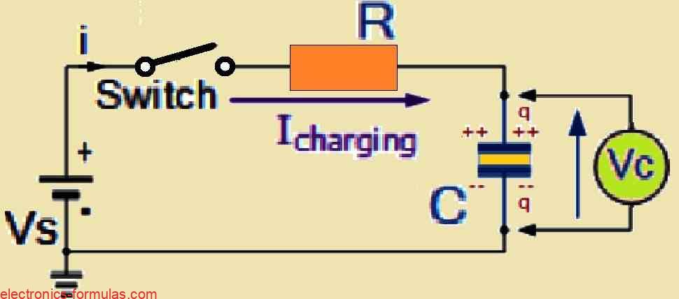
Referring to the circuit design above, assume that we have a capacitor C and a resistor R connected in series to form an RC charging circuit. This entire arrangement is connected to a DC battery which we will refer to as Vs, and is controlled by a mechanical switch.
Now, when we close the switch, which we will name as time zero, the capacitor does not immediately charge up. Instead, it progressively builds up charge through the resistor until the voltage across the capacitor almost equals the battery voltage.
If we take a step back and assume that the capacitor C is fully “discharged” and that the switch S is fully open, these would revert our circuit to the initial conditions.
So at time t = 0, there is no current (i = 0) and no charge (q = 0). But as soon as we close the switch, time starts ticking from t = 0 and the current begins to flow into the capacitor, but only through the resistor.
Since the capacitor has no voltage across it at the start (which means Vc = 0 at t = 0), the capacitor initially behaves like a short circuit for the rest of the system.
This allows the maximum current to flow through the circuit and the only thing limiting that current is the resistor R.
Using Kirchhoff’s voltage law (KVL), we can break down the voltage drops across the circuit using the following formula:
Vs – R * i(t) – Vc(t) = 0.
We can simply interpret this formula as, the total voltage from the battery equals the voltage drop across the resistor plus the voltage across the capacitor.
At this point, the current flowing through the circuit is called the Charging Current. We can calculate this using Ohm’s law with the equation: i = Vs/R which basically tells us that the initial current is equal to the battery voltage divided by the resistance of the resistor.
In short, when the switch is closed, the circuit starts charging up the capacitor. But the process takes time and depends on the values of the resistor and the capacitor. The current is highest at the beginning and then it gradually decreases as the capacitor charges.
Graph to show the RC Charging Circuit Curves


When we talk about how the capacitor (C) charges up, we use a special graph to illustrate the process. As can be seen, in the start of this process, the charge rate is really high which is why the slope of the RC charging curve is significantly steeper at first.
However as time passes and the capacitor absorbs more charge, the charging rate starts decreasing. The curve begins to level out as the capacitor takes up additional charge at a slower rate. This slowdown occurs exponentially which means that the process becomes increasingly sluggish with time.
As the capacitor fills up with charge, the potential difference (which is basically the voltage) across its plates starts to increase.
But here is something interesting, the actual time it takes for the charge on the capacitor to reach 63% of its full charge (that is 63% of the maximum possible voltage the capacitor can reach) is called one full Time Constant (T).
On the graph this 63% value is represented as 0.63Vs where Vs is the supply voltage.
We call this 0.63Vs point on the graph as “1T” which stands for one time constant. The capacitor will keep charging up beyond this point, but as it does, the difference between the supply voltage (Vs) and the voltage across the capacitor (Vc) starts to become less and less.
As this happens, the current in the circuit (i) also drops. Eventually after a long enough time (specifically after more than five time constants or 5T), the capacitor is considered to be fully charged.
By this point, time is essentially infinite (t = ∞) and the current (i) has dropped to zero, meaning there is no more current flowing in the circuit.
The capacitor is now acting like an open circuit with the entire supply voltage across its plates, so Vc = Vs.
Mathematically speaking, the time it takes for a capacitor to charge up to one time constant or 1T, can be calculated using the RC Time Constant formula which is written as:
RC Time Constant, Tau
τ = R * C
This formula tells us how quickly the capacitor charges, with R representing the resistance in ohms (Ω) and C being the capacitance in farads (F).
Since the voltage across the capacitor V is related to the amount of charge on the capacitor (which is given by the equation Vc = Q/C), we can figure out the voltage at any moment during the charging process.
The formula for the voltage across the capacitor (Vc) at any given point in time is:
Vc = Vs[(1 – e(-t/RC)]
Here is what everything in this formula means:
– Vc is the voltage across the capacitor at that specific time.
– Vs is the supply voltage from the battery or power source.
– e is a special number known as Eulers number, which is approximately 2.7182.
– t is the amount of time that has passed since the voltage was first applied to the circuit.
– RC is the time constant for the circuit, which depends on the values of the resistor and capacitor.
So basically this formula helps us to calculate the voltage across the capacitor as it gradually charges up over time.
Next, after a time that may be equivalent to 4 time constants or 4T, the capacitor is considered to be almost fully charged.
At this point the voltage that has built up across the capacitor’s plates has reached about 98% of its maximum possible value which is 0.98Vs (Vs being the supply voltage). This time period where the capacitor is still charging up but has almost reached its final 4T value, is called the Transient Period.
Then after the time reaches 5T, meaning after five time constants have passed, the capacitor is said to be completely and fully charged. At this stage the voltage across the capacitor which we call Vc, is almost equal to the supply voltage Vs.
Since the capacitor is now fully charged we have no more current flowing in the circuit. Meaning, now the charging current (Ic) drops to zero.
At this point no more charge is being added, and the capacitor is just holding its charge. This particular period which comes after the 5T mark when everything has settled down, is called the Steady State Period.
Next, we can use a table to show how the percentage of voltage and current for the capacitor in this RC charging circuit changes over time for a given number of time constants. This helps us see how quickly or slowly the capacitor reaches its fully charged state over time.
Table to Analyze the RC Time Constant
| Time Constant | RC Value | Percentage of Maximum | |
| Voltage | Current | ||
| 0.5 time constant | 0.5T = 0.5RC | 39.3% | 60.7% |
| 0.7 time constant | 0.7T = 0.7RC | 50.3% | 49.7% |
| 1.0 time constant | 1T = 1RC | 63.2% | 36.8% |
| 2.0 time constants | 2T = 2RC | 86.5% | 13.5% |
| 3.0 time constants | 3T = 3RC | 95.0% | 5.0% |
| 4.0 time constants | 4T = 4RC | 98.2% | 1.8% |
| 5.0 time constants | 5T = 5RC | 99.3% | 0.7% |
There’s one thing you might notice is that, the charging curve for an RC charging circuit doesnt go up in a straight line. It is actually exponential.
This means that, in reality the capacitor never truly reaches a full 100% charge, no matter how long you leave it charging.
But for practical purposes, after five time constants (5T) the capacitor reaches about 99.3% of its maximum charge. So at this point we just consider the capacitor to be fully charged, even though it is technically just a little bit short of 100%.
Now because the voltage across the capacitor, which we call Vc, is constantly changing as time passes, its value is different at each point in time, and especially at each time constant leading up to 5T.
This makes it possible for us to calculate the exact value of the capacitor’s voltage Vc, at any specific point in time, if we wanted to know it at a certain moment in the charging process.
So if you need to know how charged the capacitor is at any given time, you can easily calculate it, as further explained in the following example with calculations:
Solving an RC Time Constant Circuit Problem
Consider the Resistor, Capacitor, RC design as shown in the following circuit diagram:


So let us calculate the RC time constant τ for the above circuit design:
We can dettermine τ using the formula:
τ = R * C in seconds.
Therefore we get: τ = R * C = 100 k x 470 uF = 100000 * 0.00047 = 47 Seconds
a) What is the voltage across the capacitor’s plates when we are exactly at 0.7 time constants?
When we are at 0.7 time constants or 0.7T, the voltage across the capacitor (Vc) is equal to 0.5 times the supply voltage (Vs). So in this case since Vs is 6 volts, we can calculate it like this: Vc = 0.5 * 6V, which gives us Vc = 3V. So at 0.7 time constants, the voltage across the capacitor would be 3 volts.
b) What about at 1 time constant? What is the voltage across the capacitor then?
At exactly 1 time constant or 1T, the voltage across the capacitor (Vc) reaches 63% of the supply voltage which is written as Vc = 0.63Vs. Therefore using the same 6V supply voltage as before, we can calculate it: Vc = 0.63 x 6V, which gives us Vc = 3.78V. So after 1 time constant, the voltage across the capacitor would be about 3.78 volts.
c) How long will it take for the capacitor to become “fully charged” from the supply?
We have learned that the capacitor is considered to be fully charged after 5 time constants or 5T.
Since we already know from our RC calculations that 1 time constant (1T) equals 47 seconds, we can easily figure out the time for 5 time constants by multiplying: 5T = 5 * 47, which gives us 235 seconds.
So it will take 235 seconds for the capacitor to become fully charged.
d) And finally what will the voltage across the capacitor be after 100 seconds?
To calculate this we will use the voltage formula which is Vc = V(1 – e(-t/RC)).
So in our case this becomes: Vc = 6(1 – e(-100/47)).
Here is what all the values mean:
- V is the supply voltage, which is 6 volts
- t is the time, which is 100 seconds
- RC is the time constant, which we calculated earlier as 47 seconds.
Now let us calculate it step by step:
Vc = 6(1 – e(-100/47)) = 6(1 – e(-2.12)) = 6(1 – 0.120) = 6 * 0.88 = 5.28 volts.
So after 100 seconds, the voltage across the capacitor would be about 5.28 volts.
In our next tutorial we will learn more about the current, voltage relationship of a capacitor when it is discharging.
We will take a closer look at what happens to the voltage and current as the capacitor starts to lose its charge. Specifically we will concentrate on the discharging curves that are associated with this process.
We will examine what happens when the capacitor plates are directly shorted circuited together. Meaning that the stored energy in the capacitor is allowed to flow out quickly.
And we will see how that affects the voltage and current over time. This will help us to understand how a capacitor behaves, when it is releasing its stored energy.
References:
Charging and discharging a capacitor: RC circuits