
In today’s world showing numbers and letters on multiple LED displays is pretty simple, thanks to microcontrollers like Arduino or Raspberry Pi. With just a small piece of code we can easily display the digits we need. But as electronics students or hobbyists there are times when we need to show multiple numbers or digits […]
Circuits
Understanding MOD Counters or Cascaded Counter Circuits
A counter mainly works by adding one to its value every time it gets a pulse from the clock signal. When a counter counts up in response to the clock, we say it is in “count-up” mode. If it counts down instead, we call that “count-down” mode. There are also special counters that can do […]
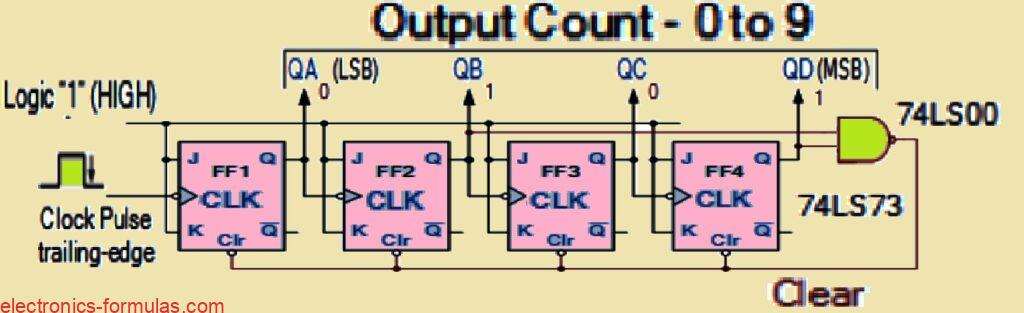
Understanding Various BCD Counter Circuits

We know that toggle T-type flip-flops can work as standalone divide-by-two counters. By connecting several toggle flip-flops in a sequence, we can create a digital Binary-Coded Decimal (BCD) counter. This counter can store or display the frequency of a specific counting sequence. Clocked T-type flip-flops act as binary divide-by-two counters. In asynchronous counters, the output […]
Understanding Synchronous Counter Circuits

In asynchronous counters we find the output of one stage connects directly to the clock input of the next stage. This setup causes a problem called “Propagation Delay.” Here the timing signal is delayed slightly as it passes through each flip-flop. In contrast synchronous counters have all their stages clocked together at the same time. […]
Analyzing Waveforms Generated by RC Circuits
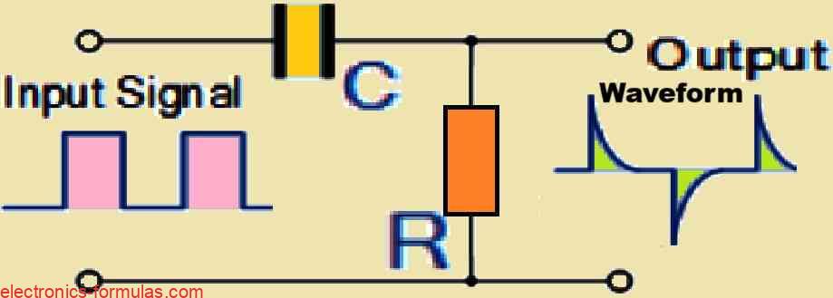
RC circuits have the ability to create various output shapes or waveforms, depending on the type and frequency (or period) of the signal applied to the input terminals. It is similar to how the circuit “reacts” differently based on what is provided to it. In earlier lessons on RC Charging and Discharging we learned that […]
Understanding Quartz Crystal Oscillator Circuits, with Calculations
Quartz crystal oscillators allow us to overcome a number of issues that may have a substantial impact on the frequency stability of an oscillator circuit. These influences include, but are not restricted to, temperature variations, fluctuations in the load connected to the oscillator, and even changes in the DC power supply voltage. All of these […]