• Skip to main content
  • Skip to primary sidebar

Electronics Calculations

Tested Electronics Formulas.

Blog | About | Contact | Privacy-Policy

Explained

LC Oscillator Circuits: Explained with Calculations

September 23, 2024 by Admin-EF 2 Comments

An LC oscillator is a circuit which we can use to transform a direct current (DC) supply voltage into an alternating current (AC) output waveform. This output can exhibit various types of waveform shapes and frequencies which might range from complex forms to simple pure sine waves depending on the specific application requirements. These oscillators […]

Filed Under: Oscillator Circuits Tagged With: Calculations, Circuits, Explained, LC, Oscillator

Band Stop Filter Circuit: Explained with Formulas

August 9, 2024 by Admin-EF Leave a Comment

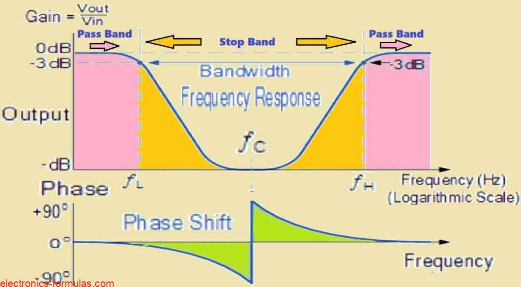
Another name for a band Stop Filter is the Notch Filter, which is designed to block and reject all frequencies that fall between its two cut-off frequency points, however all frequencies that are on the outer sides of this range, are allowed to pass through. A straightforward band-pass filter is created when we combine a simple […]

Filed Under: Filter Circuits Tagged With: Band, Explained, Filter, Formulas, Stop

Active High Pass Filter Circuits Explained with Calculations

July 19, 2024 by Admin-EF Leave a Comment

Although the fundamental filtering mechanism continues to be the same as in the passive RC filter, the active high-pass filter (HPF) integrates an operational amplifier (op-amp) to provide some essential characteristics. Gain & Control: The op-amp amplifies and controls the gain response of the filter. This is a huge benefit over passive high-pass filters, which […]

Filed Under: Filter Circuits Tagged With: Active, Circuits, Explained, Filter, High, Pass

Norton’s Theorem: Working and Calculations Explained

May 6, 2024 by Admin-EF Leave a Comment

Nortons Theorem, like Thevenin’s Theorem, offers a technique for streamlining complex circuits. It enables us to swap out complicated circuits with much simpler equivalents that just require one resistor and one source of current or voltage. This equivalent circuit is made up of, In basic terms, Norton’s Theorem reduces a complicated network of wires, resistors, […]

Filed Under: DC Circuits Tagged With: Calculations, Explained, Norton, Theorem, Working

  • « Go to Previous Page
  • Page 1
  • Interim pages omitted …
  • Page 3
  • Page 4
  • Page 5

Primary Sidebar

Categories

  • AC Circuits (23)
  • Amplifier Circuits (17)
  • Counter Circuits (7)
  • DC Circuits (20)
  • Filter Circuits (13)
  • Logic Gate Circuits (10)
  • Oscillator Circuits (8)
  • RC Circuits (6)
  • Transformers (8)
  • Transistors (10)

Recent Posts

  • Understanding BJT Common Collector Amplifier Circuit with Formulas
  • BJT Phase Splitter Circuit Explained
  • BJT Common Base Amplifier Circuit Explained
  • Explained: Class AB Amplifier Circuits
  • Understanding MOSFET Amplifier Circuit

Copyright © 2025 electronics-formulas.com