Before we begin our tutorial on active band pass filter circuits, let’s first look at the passband characteristics of several filter types. Low-Pass Filters (LPFs): An LPF’s passband begins at 0 Hz (DC) and extends to the set cut-off frequency (fC). This cut-off frequency corresponds to -3 dB with respect to the maximum passband gain. […]
Pass
Active High Pass Filter Circuits Explained with Calculations
Although the fundamental filtering mechanism continues to be the same as in the passive RC filter, the active high-pass filter (HPF) integrates an operational amplifier (op-amp) to provide some essential characteristics. Gain & Control: The op-amp amplifies and controls the gain response of the filter. This is a huge benefit over passive high-pass filters, which […]
Understanding Active Low Pass Filter Circuit with Calculations
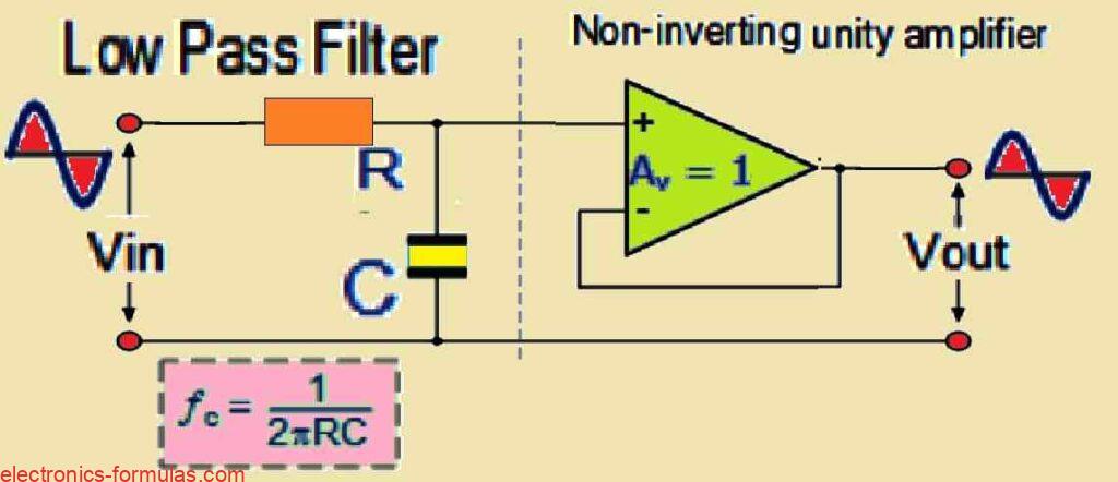
As we learned in our previous tutorial, passive filter circuits depend exclusively on passive components such as resistors (R) and capacitors (C) to provide filtering characteristics. A simple example is a first-order low pass filter built with a series resistor and a shunt capacitor across a sinusoidal input. Active filters on the other hand use […]
Understanding Passive Band Pass Filter with Formulas
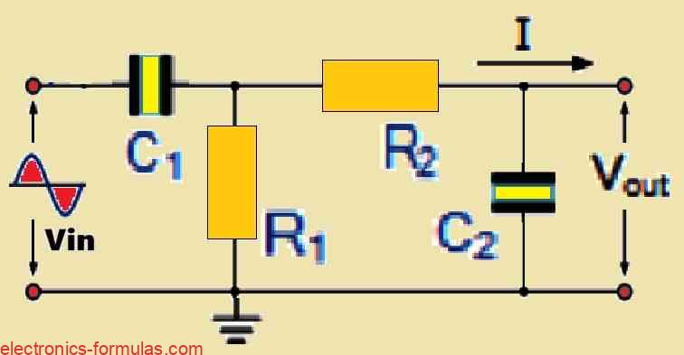
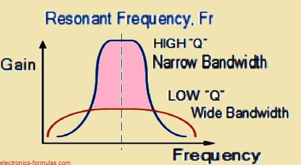
The purpose of passive band pass filters is to filter or isolate particular frequencies within a given band. As a result, undesired frequencies outside of the intended range can be attenuated while the right frequencies can flow through selectively. As was previously noted, a non-polarized capacitor and a single series resistor may be used to accurately […]
Understanding Passive High Pass Filter with Formulas
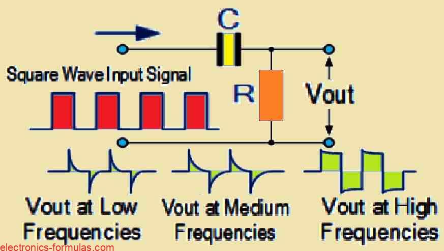
As we already know, a low-pass filter selectively permits signals with frequencies lower than its cutoff frequency fc to pass through. This shows that although the high-frequency elements of the input signal are attenuated (weakened), the lower-frequency elements are retained in the output. A passive high-pass filter, on the other hand, functions in the opposite […]
Learning Passive Low Pass Filter Circuit Calculations
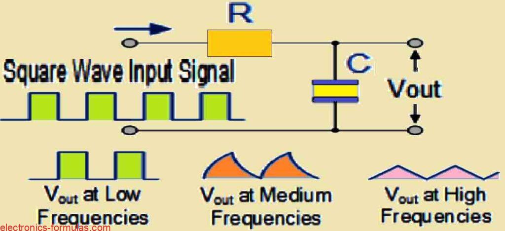
Basically passive RC filters are circuits that separate various frequencies within a signal. We can consider a signal as a collection of distinct-pitched noises. We can make an RC filter to only allow high-pitched sounds to pass through (such as a treble filter) or only the low-pitched sounds to pass through (similar to a bass […]