• Skip to main content
  • Skip to primary sidebar

Electronics Calculations

Tested Electronics Formulas.

Blog | About | Contact | Privacy-Policy

Understanding

Understanding Butterworth Filter Circuits with Formulas

August 2, 2024 by Admin-EF Leave a Comment

We know that the Butterworth filter is a useful tool for electronics professionals but there is a trade-off with its performance. It is superior to other filter types in that it produces a completely flat response in the passband and stopband, but this ideal characteristic comes at the price of a wider transition band. This transition […]

Filed Under: Filter Circuits Tagged With: Butterworth, Circuits, Filter, Formulas, Understanding

Understanding Second Order Filter Circuits with Formulas

August 1, 2024 by Admin-EF Leave a Comment

Second-order filters, often known as VCVS filters since their operational amplifier works like a Voltage Controlled Voltage Source amplifier, are a critical category in active filter design. These serve as fundamental elements for the construction of higher-order filter circuits, extending on previously researched active first-order RC filters. Our analysis of analog filters has included both passive […]

Filed Under: Filter Circuits Tagged With: Circuits, Filter, Formulas, Order, Second, Understanding

Understanding Active Band Pass Filter Circuits with Formulas

July 28, 2024 by Admin-EF Leave a Comment

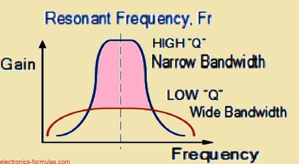
Before we begin our tutorial on active band pass filter circuits, let’s first look at the passband characteristics of several filter types. Low-Pass Filters (LPFs): An LPF’s passband begins at 0 Hz (DC) and extends to the set cut-off frequency (fC). This cut-off frequency corresponds to -3 dB with respect to the maximum passband gain. […]

Filed Under: Filter Circuits Tagged With: Active, Band, Circuits, Filter, Pass, Understanding

Understanding Active Low Pass Filter Circuit with Calculations

July 14, 2024 by Admin-EF 2 Comments

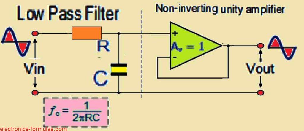
As we learned in our previous tutorial, passive filter circuits depend exclusively on passive components such as resistors (R) and capacitors (C) to provide filtering characteristics. A simple example is a first-order low pass filter built with a series resistor and a shunt capacitor across a sinusoidal input. Active filters on the other hand use […]

Filed Under: Filter Circuits Tagged With: Active, Calculations, Filter, Pass, Understanding

Understanding Passive Band Pass Filter with Formulas

July 8, 2024 by Admin-EF Leave a Comment

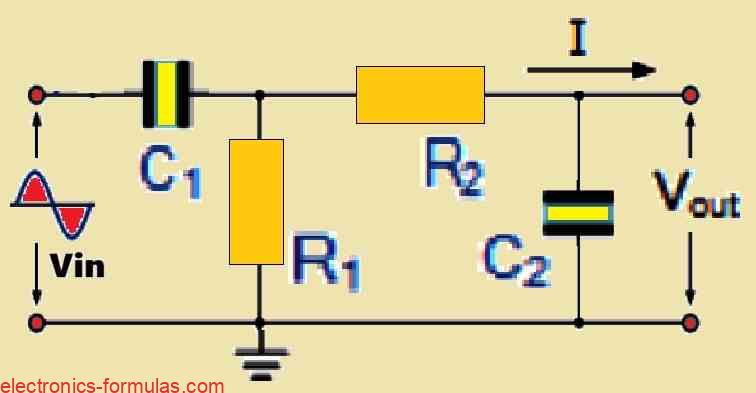
The purpose of passive band pass filters is to filter or isolate particular frequencies within a given band. As a result, undesired frequencies outside of the intended range can be attenuated while the right frequencies can flow through selectively. As was previously noted, a non-polarized capacitor and a single series resistor may be used to accurately […]

Filed Under: Filter Circuits Tagged With: Band, Filter, Formulas, Pass, Passive, Understanding

Understanding Passive High Pass Filter with Formulas

July 4, 2024 by Admin-EF Leave a Comment

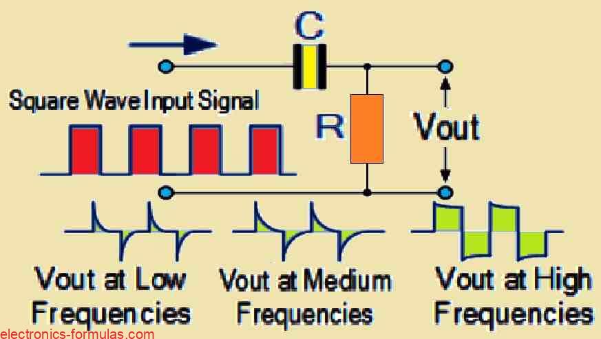
As we already know, a low-pass filter selectively permits signals with frequencies lower than its cutoff frequency fc to pass through. This shows that although the high-frequency elements of the input signal are attenuated (weakened), the lower-frequency elements are retained in the output. A passive high-pass filter, on the other hand, functions in the opposite […]

Filed Under: Filter Circuits Tagged With: Filter, Formulas, High, Pass, Passive, Understanding

  • « Go to Previous Page
  • Page 1
  • Interim pages omitted …
  • Page 3
  • Page 4
  • Page 5
  • Page 6
  • Page 7
  • Page 8
  • Go to Next Page »

Primary Sidebar

Categories

  • AC Circuits (23)
  • Amplifier Circuits (17)
  • Counter Circuits (7)
  • DC Circuits (20)
  • Filter Circuits (13)
  • Logic Gate Circuits (10)
  • Oscillator Circuits (8)
  • RC Circuits (6)
  • Transformers (8)
  • Transistors (10)

Recent Posts

  • Understanding BJT Common Collector Amplifier Circuit with Formulas
  • BJT Phase Splitter Circuit Explained
  • BJT Common Base Amplifier Circuit Explained
  • Explained: Class AB Amplifier Circuits
  • Understanding MOSFET Amplifier Circuit

Copyright © 2025 electronics-formulas.com