
I have personally used the Twin-T RC oscillators a lot and I find it very interesting, mainly because it is designed to generate a sinewave output. It is ideal for fixed-frequency applications much like the Wien-bridge oscillator. The name “Twin-T” oscillator comes from the fact that it employs two “Tee”-shaped RC networks in the feedback loop, which are connected to an inverting amplifier’s output and input, respectively. That is where the name came from.
As we already know, oscillator circuits are basically amplifiers with positive feedback. To keep the oscillations going, they need a fixed amount of voltage gain, and the Twin-T is no different. It follows the same basic principle as other oscillators.
The main aspect in this type of configuration is the feedback provided by the twin-T RC network. It takes some portion of the output signal and feeds it back to the amplifier’s input creating a 180-degree phase shift and then the amplifier stage adds another 180 degrees to it. When combined together they generate a total of 360 degrees of phase shift which enables the oscillations to continue without fading out.
One feature of the Twin-T oscillator circuit that looks so attractive is how differently it is designed, unlike other oscillators. For example, the standard RC phase-shift oscillator have resistors and capacitors arranged in a kind of ladder structure, while in the Wien-bridge oscillator circuit we have a bridge configuration. But the Twin-T oscillator does something different. It uses a passive RC network with two interconnected “T” sections. These sections have the resistors and capacitors in opposite formations and are connected in parallel.
Understanding the Twin-T RC Network Configuration

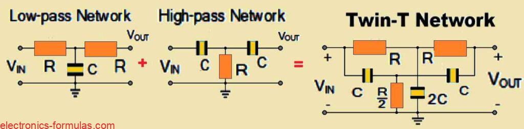
So what is really interesting in the above diagram is that one of the RC passive networks in the Twin-T oscillator has a low-pass response while the other one has a high-pass response.
This kind of setup might sound familiar because it is something we have already explored in the context of a Notch Filter.
But there is an important difference this time around. Instead of just using a single RC network we are combining two of these parallel T-shaped RC networks to create a notch-type response. This notch has a center frequency ƒc which is the exact frequency we want to oscillate at, also known as the “null frequency” of oscillation.
The neat thing about this is that oscillations are restricted to the notch frequency. In other words, oscillations can not happen at frequencies higher or lower than this tuned notch frequency because of the negative feedback that’s being fed back into the system through the twin-T network. This negative feedback effectively blocks out all other frequencies except the one we’re tuning for.
However at the precise notch frequency, the negative feedback becomes so small that it hardly has any effect. This lets the positive feedback, provided by the amplifier, take control. Once that happens oscillations occur at just this one frequency. That is different from something like the Wien bridge oscillator, which can be adjusted to operate over a broad range of frequencies. The Twin-T oscillator is locked into that single, specific frequency.
The twin-T network in this oscillator is responsible for selectively allowing this frequency to come through. It gives us an output transfer function where the frequency, depth, and phase shift of the notch are all dictated by the values of the components we have used. These individual networks in the RC system follow specific mathematical equations that define how they behave, as indicated below:
For the low-pass R-C-R network:
fC = 1/2π[√(1/C + 1/C)/(2C * R2)]
For the high-pass C-R-C network:
fC = (1/2π)√[1/{(C2 * R/2) * (R + R)}]
The final equation for the null or center frequency of the notch that causes oscillations in a twin-T network may be obtained by combining the above two sets of equations, as shown below:
fC = 1/2πRC
- In the above formula:
- fC represents the frequency of oscillations in Hertz
- R indicates the feedback resistance in Ohms
- C indicates the feedback capacitance in Farads
- π (pi) as we know is a constant with a value of about 3.142
Once we have figured out the twin-T network for the oscillator which gives us the necessary 180 degrees of phase shift at the null frequency (this happens between -90 degrees and +90 degrees, unlike the Wien-bridge oscillator that works from 0 to 180 degrees), the next step is setting up an amplifier circuit to provide the voltage gain we need.
In the Twin-T oscillator circuits, the best way to go is by pairing the RC feedback network with an operational amplifier (op-amp). Op-amps tend to work better than transistors for this kind of oscillator because they have high input impedance which really suits the characteristics of the twin-T design.
Understanding Amplification in Twin-T Networks
Operational amplifiers are ideal for twin-T oscillators because they can deliver a high voltage gain, have high input impedance and offer low output impedance. These qualities make them excellent at driving the oscillator. Now, at the oscillating frequency which we call ƒc, the feedback gain almost drops to zero.
So to keep the oscillator running, we need an amplifier that can provide a voltage gain much greater than unity (or one). The positive feedback necessary for the oscillation is provided by a feedback resistor R1, while another resistor R2, is there to ensure the circuit starts oscillating.
A good rule of thumb here is that the ratio of these two resistors should be greater than 100, so the circuit oscillates as close to the desired frequency as possible. To achieve the intended positive gain at the oscillating frequency the best is to employ a non-inverting amplifier configuration.
In this setup, a small amount of the output voltage is fed directly to the non-inverting (+) input of the op-amp using an appropriately configured potential divider resistive network. Meanwhile, the negative feedback produced by the twin-T oscillator circuit is fed into the inverting (–) input of the op-amp.
This whole closed-loop configuration creates a non-inverting oscillator circuit that not only gives us excellent stability but also provides a very high input impedance and a low output impedance. This combination of features helps ensure smooth, consistent oscillation at the desired frequency, as shown in following diagram of a twin-T oscillator setup.
Analyzing a Op-Amp Based Twin-T Oscillator Circuit

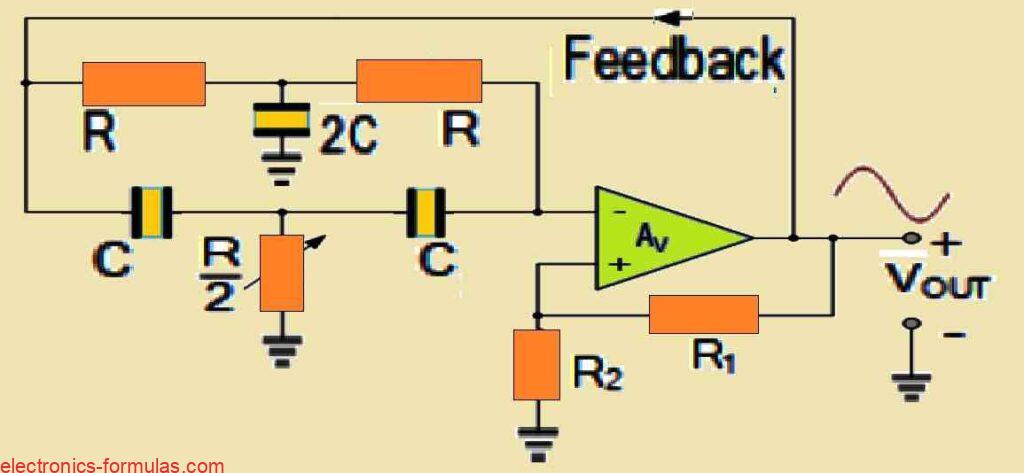
So if we look at how the twin-T oscillator works, we can see that it gets its positive feedback through the non-inverting input of the amplifier. This positive feedback is delivered through a voltage divider network, which is actually the main element to keeping the oscillations going.
On the other side, the negative feedback which helps to stabilize and control the frequency, comes from the twin-T RC network.
Now if we want to make sure that the circuit oscillates at exactly the right frequency (that one specific frequency we have tuned it for), we can use the “Tee-leg” resistor which is represented as R/2.
A really handy way to handle this is by using an adjustable trimmer potentiometer for this resistor. This allows for fine-tuning.
Not only can you adjust it to lock in the exact oscillating frequency but you can also use it to compensate for any slight variations or tolerances in the capacitors.
Sometimes the components like capacitors have small imperfections or tolerances that can shift the frequency slightly, and this adjustable resistor lets you correct for that. In that way, the circuit will start oscillating correctly right from the beginning and stay at the desired frequency.
Solving a Twin-T Oscillator Problem #1
Let us say we have to create a twin-T oscillator circuit that can generate a 1.5 kHz sinusoidal output signal, which is widely used in electronic circuits. We will utilize an operational amplifier with a gain ratio of 200 to do this, meaning that the op-amp will provide sufficient amplification to maintain the oscillator operating smoothly at the intended frequency.
Finding the values of the two essential parts, the resistors (R) and capacitors (C), will decide the oscillation frequency which in this problem is set at 1.5 kHz. Since we realize that the oscillation frequency is dependent on both the resistors and the capacitors, we can use a standard formula to get the required values.
Now let us pick a reasonable value for the two feedback resistors R. A good choice here is 12 kΩ for each resistor. It is important to remember that in this type of twin-T oscillator, these two resistors must have exactly the same values for the circuit to work properly and oscillate at the right frequency. Once we have determined and fixed these resistor values we can then move on to calculate the value of the capacitors.
To determine the capacitance, we will apply the following formula that relates the frequency of oscillation (set to 1.5 kHz) to the values of R and C.
fC = 1/2πRC = 1.5 kHz = 1500 Hz
1500 = 1/2 * π * 12000 * C
∴ C = 1/2 * π * 12000 * 1500 = 0.00000000884194128 Farads
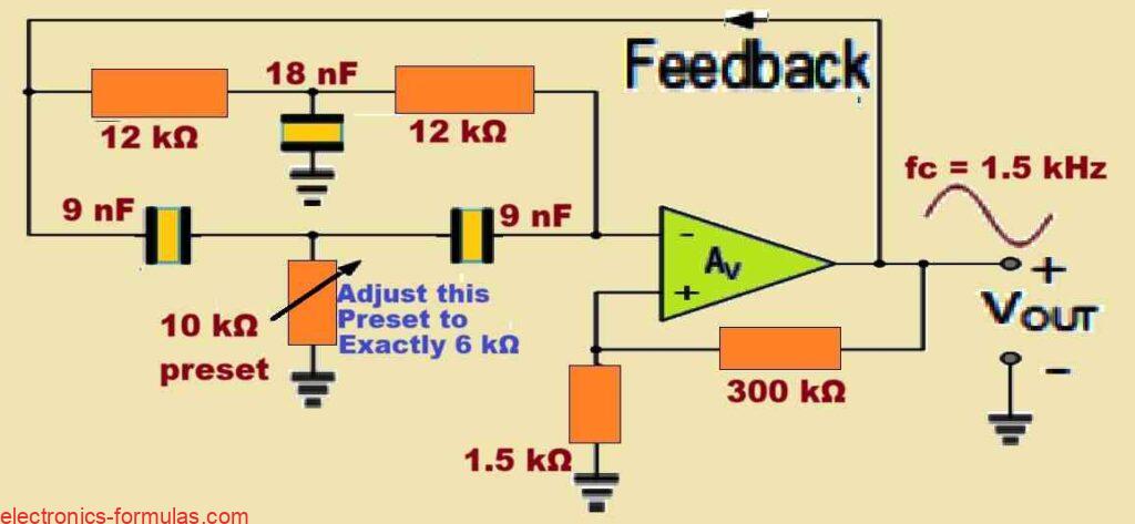
∴ C = 8.841941 nF = 9 nF
Therefore with our value for R = 12 kΩ, and C = 9 nF, we can determine the value of the center Tee-leg capacitor as 2C = 2 x 9 nF = 18 nF
Now, as we discussed previously the loop gain of the op-amp IC must be around 200, so suppose we select the value for R2 as 1.5 kΩ then resistor R1 will be 1.5 * 200 = 300kΩ.
Now, from our previous discussions we know that the value of the preset or the potentiometer should be 50% of R, or simply R/2. Since in our existing problem, the value of R is 12 kΩ, so the we have to adjust it to the precise value of 12/2 = 6 kΩ.
So, now it is possible for us to draw the full circuit diagram for our op-amp based Twin-T Oscillator circuit, with the precise components values as per the above solved calculations, as shown below:
Conclusions
Alright, so to sum up what we have learned about Twin-T Oscillator circuits, these circuits are pretty easy to build using just a few passive components (like resistors and capacitors) along with an operational amplifier.
The crucial aspect to how this circuit works is the tuned RC network used in the feedback loop. This network is designed to produce the sinusoidal output waveform that we are after.
The circuit gets it’s name “Twin-T” because it uses two T-shaped RC networks that are connected in parallel. These two networks operate in anti-phase, meaning they cancel each other out at a specific frequency, called the null frequency.
At this null frequency, the output is zero. But at all other frequencies you get some output. One cool thing about this setup is that the circuit will not oscillate at any frequency other than the one it’s tuned to.
This is because the negative feedback coming through the twin-T RC network stops oscillations above or below the tuned frequency.
But when the circuit hits that perfect null frequency, the voltage at the non-inverting input of the op-amp is in phase with the output voltage. This alignment is what makes the circuit continue oscillating at the desired frequency.
Now if you want to make sure the circuit oscillates as close to the null frequency as possible, you can use a trim-pot (a small adjustable resistor) in the tee-leg of the low-pass stage.
This lets you fine-tune the RC network to make sure the circuit starts up properly and gives you a nice, clean sine wave output. One downside of the Twin-T oscillator though, is that its oscillation frequency and the quality of the sine wave it produces really depends on how well the resistors and capacitors in the twin-T network interact with each other.
That means you need to be really precise with the values of these components. If they are even a little off, the circuit might not oscillate at the right frequency, or the output waveform might not be as clean as you want. So picking the right components is super important for getting the best performance out of a twin-T oscillator.
References: Twin-T Oscillator