As we learned in our previous tutorial, passive filter circuits depend exclusively on passive components such as resistors (R) and capacitors (C) to provide filtering characteristics. A simple example is a first-order low pass filter built with a series resistor and a shunt capacitor across a sinusoidal input.
Active filters on the other hand use both active components such as operational amplifiers and passive components. These operational amplifiers provide amplification within the circuit.
One notable disadvantage of passive filters is their inherent signal attenuation, wherein the output signal amplitude is always lower than the input signal, which results in a voltage gain of less than one (unity gain). This attenuation is particularly significant in multi-stage passive filter designs.
Active filters as the name implies, actively solve this restriction by using active components such as op-amps, which receive power from an external source and use it to amplify the signal, thereby restoring or controlling signal loss in passive filters. This amplification capacity facilitates active filters to produce voltage gains that exceed unity.
In addition to restoring signal strength, filter amplification in active filters may be deliberately used to alter or shape the filter circuits frequency response. This modification may allow the production of a more selective output response. The filter’s output bandwidth can be reduced for better selectivity or widened for a larger response by varying the amplification across different frequency ranges. In a nutshell the amplification feature becomes a tool for modifying the filter’s transfer function.
As previously stated, the key distinguishing feature between passive and active filters is their amplification capabilities. Because passive filters rely entirely on passive components, they are intrinsically restricted to a voltage gain of less than one (unity gain). Active filters on the other hand, use active components such as op-amps to induce amplification, resulting in an increase in voltage that exceed unity.
It is critical to understand that even with the amplification, the maximum frequency response feasible in an active filter is not infinite. The upper limit is set by the gain-bandwidth product, GBWP of the operational amplifier, used in the circuit. The GBWP is simply a trade-off between the op amp’s open-loop gain and bandwidth, in which as the gain increases, the bandwidth will unquestionably decrease, and vice versa.
Active Filter Advantages:
Regardless of this limitation, active filters have significant benefits over passive filters.
Active filters are often thought to be easier to design and execute compared to passive filters.
Active filters might achieve improved performance features, such as superior accuracy and a steep roll-off in frequency response.
When properly built, active filters may provide more noise reduction than passive filters.
In order to maximize the positive effects of active filters, stringent circuit design strategies may be required, which involves selecting appropriate op-amps with sufficient GBWP parameters, as well as using proper component selection and layout strategies to reduce noise and assure optimal performance.
The active low pass filter (LPF) is a great illustration of how active filter design incorporates passive filter characteristics. The fundamental operating principle and frequency response of an active LPF are quite similar to those of its passive cousin, the passive RC LPF. despite this, the essential feature is the inclusion of an operational amplifier or op-amp in the active LPF circuit. This op-amp introduces amplification and allows you to regulate the gain of the filter.
Simple Active Low Pass Filter (LPF) Design:
The most fundamental type of an active LPF is to connect an inverting or non-inverting amplifier arrangement, to a basic RC LPF circuit, which we have already seen in our previous tutorials. This effectively combines the filtering properties of the passive RC network with the amplification capabilities of the op-amp. Adjusting the gain of the op-amp allows you to adapt the total gain and response of the active LPF according to particular needs
Benefits of an Active LPF Design:
Although the filtering behavior might be identical to the passive LPF, you may find various advantages in an active LPF:
Higher Gain: The op-amp provides for voltage gain larger than unity which may compensate for signal attenuation in passive filters.
Impedance Matching: Op-amp input impedance is normally high which reduces loading effects on previous circuit stages.
Improved Design freedom: The op-amp’s gain control provides more design freedom in comparison to purely passive LPF circuits.
First Order Low Pass Filter
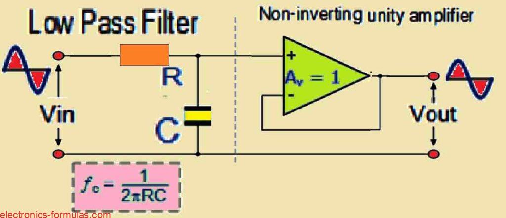
Design and Function:
This first-order active low pass filter circuit consists of a passive RC filter stage, then followed by a non-inverting operational amplifier acting as a voltage follower buffer.
Passive to Active Transition:
The passive RC stage offers a low-frequency channel for the input signal.
The voltage follower op-amp has a DC gain (Av) of +1 (unity gain), where as the preceding passive RC filter provided a gain lower than unity.
Benefits of Buffering:
High Input Impedance: The op-amp’s high input impedance reduces loading effects on the filter’s output minimizing too much signal attenuation.
Low Output Impedance: Because the op amp’s output impedance is low, fluctuations in load impedance have no effect on the filter’s cut-off frequency.
Increased Stability: Because of the buffer’s isolation, this arrangement provides excellent overall filter stability.
Limitations and alternatives:
Unity Voltage Gain: Although this design is stable, its main disadvantage is that it lacks of voltage gain above unity.
Power Gain Considerations: even though the voltage gain is unity, the power gain might be substantial due to the large differential between the op-amp’s input and output impedances.
Alternative to Higher Gain:
If a voltage gain higher than one is necessary, other active filter topologies such as the Sallen-Key LPF or Multiple Feedback LPF, can be used. These designs use the op-amp’s gain capabilities, to obtain the appropriate voltage gain while retaining the filtering characteristics.
Active Low Pass Filter with Voltage Gain Control
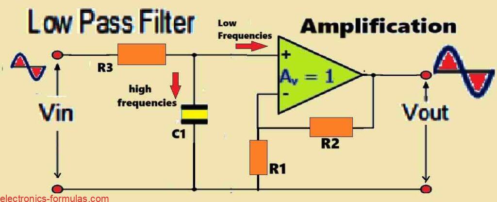
Active LPF Frequency Response and Gain Control.
The active low pass filter (LPF) has a frequency response that is very much similar to its passive RC cousin. But, one important difference is the loudness of the output signal. The active LPF includes an amplifier which introduces a passband gain Af, that substantially increases the output signal amplitude as compared to the passive filter.
Non-inverting Amplifier Gain:
The size of the voltage gain in a non-inverting amplifier design utilized within the active LPF is exactly proportional to the ratio of the feedback resistor R2 to the input resistor R1. The relationship could be represented using the formula below:
DC Gain = 1 + (R2 / R1)
The above equation shows that the active LPF’s DC gain is not restricted to unity (1) as found in the passive filter, and simply by altering the values of R2 and R1, the engineer is able to change the filter’s Af to adjust the output signal amplitude to his specific needs.
As a result, the frequency-dependent gain of an active low pass filter can be determined using the following formula:
Voltage Gain (Av) = Vout / Vin = AF / √[1 + (f / fc)2]
- In the above formula,
- AF, denotes the pass band gain of the filter, (1 + R2/R1)
- f, represents the frequency of the input signal in Hertz, (Hz)
- fc, indicates the cut-off frequency in Hertz, (Hz)
Therefore, the frequency gain equation above may be used to verify the working of a low-pass active filter in the following manner:
- At very low frequencies, f < fc Vout / Vin ≅ AF
- At the cut-off frequency, f = fc Vout / Vin = AF / √2 = 0.707 AF
- At very high frequencies, f > fc Vout / Vin < AF
The active low pass filter (LPF) has a specific gain response which are characterized through the following main points:
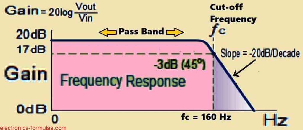
Constant Passband Gain (Af): The filter provides a constant gain of Af between 0 Hz and the high frequency cut-off point (fc).
Gain Roll-off at fc: Around the cut-off frequency (fc), the gain drops to 0.707 Af.
-20 dB per decade. Roll-off: After fc, the gain declines at a steady rate of -20 dB per decade as the frequency increases. This means that every tenfold (one decade) increase in frequency reduces the voltage gain by a factor of ten.
In filter circuits, the magnitude of the passband gain is usually given in decibels (dB) as a function of voltage gain. Below shown is the formula that makes this conversion easier:
Voltage Gain Magnitude in (dB)
Av(dB) = 20log10(Vout / Vin)
∴ -3dB = 20log10[0.707(Vout / Vin)]
Solving an Active Low Pass Filter Problem#1
Design a non-inverting active low pass filter circuit that has the following specifications:
Specifications:
- Gain: Achieve a gain of 10 (Av = 10) at low frequencies (within the passband).
- Cut-off Frequency: Set the high frequency cut-off point (fc) to 160 Hz.
- Input Impedance: Maintain an input impedance of 12 kΩ (Zin = 12 kΩ).
- Topology: Utilize a non-inverting amplifier configuration.
The voltage gain of a non-inverting operational amplifier can be calculated using the following formula:
AF = 1 + R2 / R1 = 10
Let’s imagine a value of 1kΩ for resistor R1, then reorganizing the formula above yields the following value for R2:
R2 = (10 – 1) * R1 = 11 * 1 = 9kΩ
Therefore, with a voltage gain of 10, we now have R1 = 1kΩ and R2 = 9kΩ. We can convert this voltage gain into an equivalent decibel dB value using the following formula:
Gain in dB = 20logA = 20log10 = 20 dB
As per the given specifications, the cut-off frequency is supposed to be 160Hz with an input impedance of 12kΩ. We can find out the value of the capacitor C required to achieve this cut-off frequency, through the following formula:
fc = 1 / 2πRC (Hz)
Here, fc = 160 Hz and R = 12kΩ
∴ C = 1 / 2π * fc * R
= 1 / (2π * 160 * 12000)
= 82.893 nF
Now, we can draw the final low pass filter circuit and frequency response as witnessed in the following images:
Final Low Pass Filter Circuit
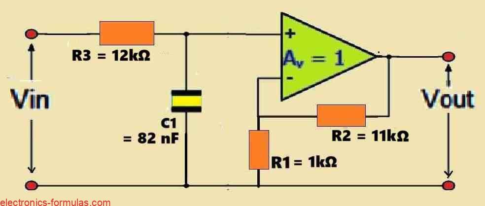
Note: The value of R2 is mistakenly shown as 11k, instead of 9k….
Frequency Response Curve
The impact of input impedance on cut-off frequency:
Variations in the external impedance connected to the filter’s input in an active filter can affect the cut-off frequency (fc) because of the interaction between components connected in series or parallel. This might cause undesired changes in the filter’s response.
Lowering Input Impedance Effects:
One way to reduce this impact is to strategically arrange the feedback capacitor in parallel with the feedback resistor (R2). This essentially eliminates it from the input path, reducing its contact with the external impedance. Furthermore, this reconfiguring preserves the filter’s overall characteristics.
Adjusting capacitance for parallel placement:
If you want to adjust the values of the RC components you may calculate them using the conventional formula for parallel capacitors, as given below:
fc = 1 / 2πCR2 Hertz
In the following examples I will discuss different first-order active low pass filter circuit configurations, let’s learn more:
Circuit Diagram for a Simple Inverting Amplifier Filter
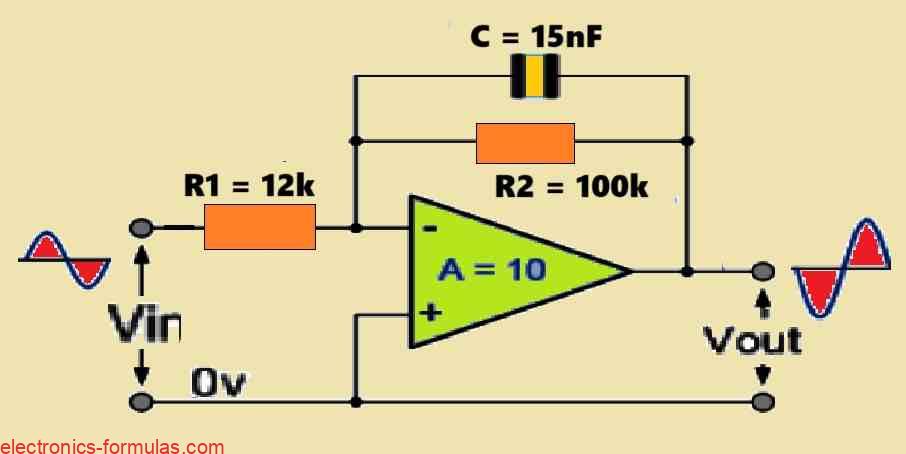
Active LPF with a modified feedback circuit (inverting configuration):
The circuit shown is an inverting active low-pass filter (LPF), with the capacitor (C) carefully shifted from the op-amp’s input to the feedback loop. According to the feedback circuit, C is connected in parallel with the resistor R2.
The impact on Frequency Response:
This parallel pairing of C and R2 is critical to setting the filter’s frequency response. Similar to the original design, here it achieves the -3 dB threshold. But there is a significant difference in behavior beyond the cut-off frequency (fC). In this improved design, the amplifiers gain shows a continuous roll-off at a rate higher than 20 dB/decade when frequency exceeds fC. This differs from the usual response, in which the roll-off becomes stable at -20 dB/decade after fC.
Gain Response at Various Frequencies:
Low Frequencies: At low frequencies, the capacitive reactance (XC) of C is considerably higher than the impedance of R2. As a result the typical inverting amplifier formula -R2/R1 basically determines the filters DC gain, which in this case is -10.
Transition to fC: As the frequency increases, the XC value gradually decreases. This drop in the XC reduces the total impedance of the parallel combination (XC||R2).
High Frequencies: At sufficiently high frequencies, the XC is reduced to a negligible level in comparison to R2. At this point, the feedback path through the capacitor C is almost removed, transforming the circuit into a simple inverting amplifier with a gain of -R2/R1.
Advantages of the Modified Design
Input Impedance: One advantage of this design is that the circuit’s input impedance is now defined exclusively by resistor R1. This facilitates an analysis of the filters interactions with preceding circuits.
Output Signal: The filter exhibits an inverting characteristic, which means that the output signal is inverted when compared to the input.
Enhanced Stability: By including the corner frequency-determining components (C and R2) in the feedback loop, the filters RC time constant, and hence the fC, become insensitive to fluctuations in source impedance. This improves the filter’s total frequency response stability.
Independent Gain and Cut-Off Frequency Control: This design also allows you to modify the DC gain and corner frequency separately. The gain may be adjusted by changing the R2 to R1 ratio, but the fC may also be managed by choosing suitable C and R2 values.
Please note that Although this improved design has unique advantages, the continuous roll-off beyond fC may not be appropriate for many applications. Depending on the filtering needs, a conventional -20 dB/decade roll-off characteristic may often be selected.
The Unity-Gain Non-inverting LPF with decreased high-frequency gain:
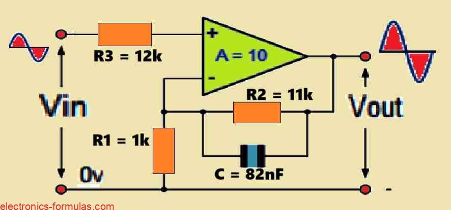
The above shown circuit demonstrates a non-inverting active low-pass filter (LPF) with a unity gain (Av = 1) response. But placing the capacitor (C) in parallel with the feedback resistor (R2) causes an unusual characteristic in the high-frequency response.
The Effect of Capacitor Placement on Gain:
At lower frequencies, the C’s capacitive reactance (XC) is considerably higher than the impedance of R2. In this mode, the capacitor serves as an open circuit within the feedback loop and the circuit behaves as a typical non-inverting amplifier with a gain of 1 + (R2/R1).
Because R2 and R1 are designed for producing a gain of one (i.e., R2 = R1), the total gain is Av = 1 + (R2/R1) = 1 + 1 = 1, just as required for the low-frequency response.
Now as the frequency increases, the XC value gradually decreases. The drop in the XC value lowers the total impedance of the parallel combination (XC||R2). At sufficiently high frequencies, the XC becomes minimal in comparison to R2. At this moment, the capacitor shorts out resistor R2, eliminating it from the feedback path. This greatly decreases the feedback to the op-amp, restricting its gain control capabilities.
Unity Gain at High Frequencies:
Because the R2 no longer influences feedback at high frequencies, the op-amp’s gain is mostly determined by its open-loop gain. But for most practical op-amps, the open-loop gain rolls off at higher frequencies, causing the filter’s overall strength to also roll off at high frequencies until it reaches about unity (0 dB). At high frequencies, the circuit essentially transforms to behave just like a voltage follower.
Applications and considerations:
Although this design produces a unity-gain LPF response, the unanticipated loss in gain at high frequencies could prove undesirable in some applications. For example in an ideal low-pass filter, we would anticipate a constant gain (in the present scenario, unity) until the corner cut-off frequency is reached, followed by a fast roll-off beyond that point.
Here are some other considerations:
The frequency at which the gain drop becomes significant is determined by the op-amps open-loop gain roll-off characteristics.
If a sharper roll-off and well-defined passband gain are required for the application, other LPF designs such as Sallen-Key filters, may be more appropriate.
In general this circuit provides a straightforward method to a unity-gain LPF, although it has limitations in its high-frequency gain response.
Improved Filter Order: From First-Order to Second-Order Active LPF.
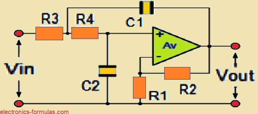
Here:
Gain Av = 1 + R2 / R1
Cut-off Frequency fc = 1 / √(2πR3R4C1C2)
A first-order active low-pass filter (LPF) can be easily converted into a second-order LPF, just like the passive filters were. This change can be achieved by adding an extra RC network to the filters input path.
The Effect on Frequency Response:
Although a second-order LPF’s overall filtering characteristics are similar to those of its first-order cousin, the stopband roll-off performance differs significantly.
The second-order LPF has a sharper roll-off rate in the stopband than the first-order filter. This sharper roll-off results in a 40 dB/decade (or 12 dB/octave) attenuation in the stopband which is two times the rate seen in first-order filters.
Design considerations:
Because of this closeness in design concepts, the essential procedures required in developing a second-order active LPF are largely the same as those used for a first-order active LPF.
However further calculations may be required to establish the component values (resistors and capacitors) needed to obtain the appropriate second-order filter characteristics, such as the cut-off frequency and quality factor (Q).
Gain Considerations for Cascaded Active LPFs:
When multiple active low-pass filter (LPF) circuits are cascaded to form higher-order filters, the total gain becomes an important factor to take into consideration. The total gain can be calculated by multiplying the individual gains from each cascaded step.
Product of stage gains:
Assume that the individual gains of the cascaded phases are:
Stage 1: Av1 = 10.
Stage 2: Av2 = 36
Stage 3: Av3 = 110.
The overall gain (Avtotal) of the cascaded filter would therefore be:
Avtotal = Av1 x Av2 x Av3 = 10 x 36 x 110 = 39,600
Av (dB) = 20log10 (39,600) = 91.95 dB
As I have shown in the above example, the overall gain is the product of the gains at each individual level of the cascaded filter.
The significance of second-order active LPFs in higher-order filter design:
Second-order (two-pole) active low-pass filters (LPFs) play a critical role in filter design since they serve as the foundation for higher-order filters. This adaptability arises from the ability to chain these second-order LPFs to one another.
Cascading to Higher Orders:
Filters with any desired order, including both odd and even values, may be constructed by carefully cascading first- and second-order active filter stages. This method enables the design of filters with specific frequency response characteristics, such as steeper roll-off rates in the stopband or the implementation of more sophisticated filtering functions.
Our next tutorial will go through the concepts of active high-pass filters. Interestingly these filters may be created with an amazingly simple modification: swapping the placements of resistors and capacitors in the circuit of the corresponding low-pass filter. This emphasizes the intrinsic relationship between these two fundamental filter types, in the context of active filter design.
References: Active Low-Pass Filter Design
i have a question for your explanation on Solving an Active Low Pass Filter Problem#1
Design a non-inverting active low pass filter circuit that has the following specifications:
Specifications:
Gain: Achieve a gain of 10 (Av = 10) at low frequencies (within the passband).
Cut-off Frequency: Set the high frequency cut-off point (fc) to 160 Hz.
Input Impedance: Maintain an input impedance of 12 kΩ (Zin = 12 kΩ).
Topology: Utilize a non-inverting amplifier configuration.
My question specifically is concerning this part ” AF = 1 + R2 / R1 = 10
Let’s imagine a value of 1kΩ for resistor R1, then reorganizing the formula above yields the following value for R2:
R2 = (12 – 1) * R1 = 11 * 1 = 11kΩ
Therefore, with a voltage gain of 10, we now have R1 = 1kΩ and R2 = 11kΩ.”
why is R2 = 11kΩ , but simple math proves it R2 = 9kΩ.
You are absolutely right, and thanks for pointing out the mistake, actually it was just typographical error, now I have corrected it in the article….thanks again!