
The Exclusive OR (XOR) Gate is a specialized type of digital logic gate that are widely utilized in digital arithmetic operations. Using these gates it becomes possible for us to calculate the sum of two binary numbers and we can also use these gates in error-detection and correction systems.
So far in our logic gate tutorials we have learned that by combining three fundamental gates such as AND, OR, and NOT, we are able to create various other logic gates, for example the NAND and the NOR gates, or maybe any other logic function we needed by us.
However there are two additional types of logic gates that are, although not fundamental by themselves because we have create them by joining other gates, yet their Boolean function are important and should be considered complete logic gates in their own rights. These composite type of gates are the Exclusive OR (XOR) Gate and the complement of this gate is the Exclusive NOR (XNOR) Gate.
In our earlier lessons we learned that while working with a 2-input OR gate, if A = “1”, OR B = “1”, or both A + B = “1” that means the digital gate will produce an output that has to be also at a logic level “1” and that is exactly why we call this type of logic gate as an Inclusive-OR function, and simply because here we find that it “includes” a situation where the output Q equals “1” specifically when both inputs A and B are “1”.
Now suppose a case in which you get an output of logic “1” when you apply ONLY A = “1” or when you apply ONLY B = “1” to the inputs, and NOT simultaneously to both the inputs which correspond to binary inputs of “01” or “10”, this gives you the output of logic “1”. With this type of response, we identify the gate as an Exclusive-OR function or simply in short an Ex-Or function. The reason for this is because its Boolean expression “excludes” the “OR BOTH” case of Q = “1” when both A and B = “1”.
To explain the above more simply, we find that the output of an Exclusive-OR gate ONLY becomes “HIGH” when we supply its two inputs with “DIFFERENT” logic levels which are opposite to each other.
When the number of logic “1’s” on its inputs are odd, that gives us a logic “1” at the gate output. We can have the two logic inputs of logic level “1” or at logic level “0” which provides us with the Boolean expression of:
Q = (A ⊕ B) = A.B +A.B
We can create an Exclusive-OR Gate function or Ex-OR, simply by joining the basic logic gates with one another to generate higher order complex gate functions which can be comprehensively implemented for configuring arithmetic logic circuits, computational logic comparators and error detection circuits.
The two-input “Exclusive-OR” (Ex-Or) gate operates in the form of a modulo two adder which means that it adds two binary values together but it implements this in a specific way, as indicated below:
Modulo Two Addition: In modulo two arithmetic, addition is performed such that if the total off it goes above 1, it wraps around to 0. In terms of binary values we can write it as:
0 + 0 = 00 + 1 = 11 + 0 = 11 + 1 = 0(the sum wraps around to 0, and a carry is ignored)
To learn more you can refer to the following information which provides the truth table, logic symbol and process of implementation of a 2-input Exclusive-OR gate:
Symbol and Truth Table for 2-input Ex-OR Gate
Symbol


Truth Table
| B | A | Q |
| 0 | 0 | 0 |
| 0 | 1 | 1 |
| 1 | 0 | 1 |
| 1 | 1 | 0 |
Boolean Expression Q = A ⊕ B, we can read this as A OR B but NOT BOTH gives Q
Getting the Boolean Expression of Q = AB+AB
Referring to the above the truth table we find that the output of an Exclusive-OR gate ONLY turns “HIGH” whenever we apply “DIFFERENT” logic levels across both of its two input terminals with reference to each other.
Suppose, we apply these two inputs A and B, with similar logic level “1” or if we supply both inputs with logic level “0” then we get an output with a logic “0” which causes the gate to become an “odd but not the even gate”. Meaning, we find that the output of this gate is “1” only when we apply an odd number of logic 1’s across the inputs.
The above explained feature of the Exclusive-OR gate to compare its two input logic levels and generate an output value which specifically depends on this input condition can be considered very helpful for engineers designing computational logic circuits, simply because this feature helps them by providing them with the following Boolean expression of:
Q = (A ⊕ B) = A.B +A.B
A 2-input Ex-OR logic gate executes a logic function which can be explained as: “A OR B but NOT both” will produce an output at Q. In a normal situation you will find that an Ex-OR gate produces an output of logic “1” ONLY when we supply an ODD number of logic 1’s at its inputs terminals, but if we supply two identical logic inputs then it produces an output logic “0”.
In this case, with more than two inputs applied we can call an Ex-OR function an “odd function” or modulo-2-sum (Mod-2-SUM), and not an Ex-OR. We can further extend this concept to implement this to any desired number of individual inputs as shown in the following example below for a 3-input Ex-OR gate.
Symbol and Truth Table for 3-input Ex-OR Gate
Symbol

Truth Table
| C | B | A | Q |
| 0 | 0 | 0 | 0 |
| 0 | 0 | 1 | 1 |
| 0 | 1 | 0 | 1 |
| 0 | 1 | 1 | 0 |
| 1 | 0 | 0 | 1 |
| 1 | 0 | 1 | 0 |
| 1 | 1 | 0 | 0 |
| 1 | 1 | 1 | 1 |
Boolean Expression for this is Q = A ⊕ B ⊕ C, which we can read as “Any ODD Number of Inputs” gives Q.
Getting the Boolean expression of: Q = (A ⊕ B) = ABC+ABC+ABC+ABC
The symbol that we use to indicate an Exclusive-OR odd function looks somewhat different to the one that is used for a typical Inclusive-OR Gate.
The Boolean expression that we use to represent a logic OR gate is essentially a form of logical addition, which is commonly denoted by the standard plus sign, which you might be already familiar with from basic arithmetic.
The symbol that we employ to describe the Boolean expression of an Exclusive-OR function is in the form of a plus sign ( + ) shown inside a circle ( Ο ).
The exclusive-OR symbol which is represented as (⊕), is also used to denote the mathematical idea of the “direct sum of sub-objects.” Thus in the context of the Exclusive-OR function, we use the symbol (⊕) to indicate this concept.
As we learned in our earlier discussions that the Ex-OR function is not a basic logic gate rather it is created through the integration of various standard logic gates joined with one another.
By implementing the above given 2-input truth table, we can further extend the Ex-OR function to: (A+B).(A.B). This indicates that we can implement this new expression using the individual gates as listed below:
Equivalent Circuit of an Ex-OR Gate


When you try to implement the above Ex-OR function design you will find that the main issue involved here is that the design has to incorporate three different types logic gates OR, NAND and lastly the AND gate.
Alternatively, a better method to create the Ex-OR function could be by involving just a single gate which is the very popular, the NAND gate, as depicted in the following section:
Creating a Ex-OR Function using NAND gates


The main purpose of Exclusive-OR Gates is to design and construct circuits which can execute arithmetic operations and calculations, that may specifically involve Adders and Half-Adders, simply because these provide us with a “carry-bit” function which work like a controlled inverter, where we are able to use one input to transfer the binary data, and use the second input to feed a control signal.
The standard digital logic Exclusive-OR gate IC’s which we can readily procure from the market are listed in the following table:
| Logic Type | Gate Type | Part Number | Description |
|---|---|---|---|
| TTL Logic | Ex-OR Gate | 74LS86 | Quad 2-input |
| CMOS Logic | Ex-OR Gate | CD4030 | Quad 2-input |
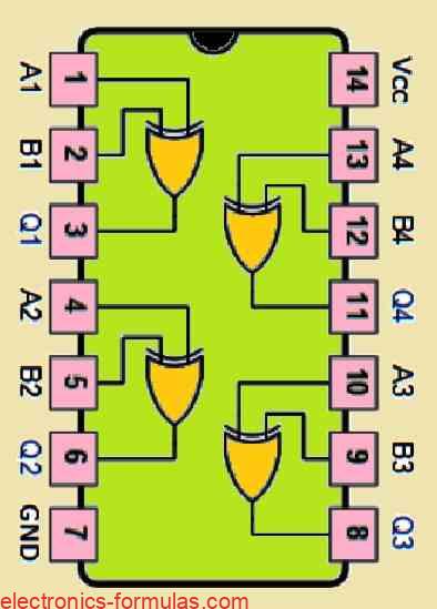
Pinout Diagram of the IC 7486 which is a common Quad 2-input Exclusive-OR Gate

Conclusions
You will find that Exclusive-OR logic function is highly valuable and could be applied in various computational circuits. Although this gate might not be a fundamental type of logic gate on its own, yet its utility and flexibility have been acknowledged to be a standard logical function, including all the specific Boolean expression, operator, and symbol. We can quickly obtain the Exclusive-OR Gate in standard packages such as the 74LS86 TTL quad two-input gate and the 4030B CMOS package.
One of the most popular implementation of these gates is in the form of a fundamental logic comparator, in which it produces an output logic “1” whenever we apply its inputs with two input different logic bits. Because of this characteristic, the Exclusive-OR gate is recognized for its inequality function, often referred to as an odd function. If you want to compare multi-bit numbers then you may require additional Exclusive-OR gates such as the IC 74LS85 logic comparator which can accommodate up to 4 bits.
In our next upcoming Digital Logic Gates tutorial, I will explain you about the Exclusive-NOR gate which are also called the Ex-NOR Gate function, and in this article I will also provide you its applications in TTL and CMOS logic circuits, and also provide you the information regarding its Boolean Algebra definition and truth tables.
References: XOR gate