
In our previous lessons about Sequential Logic we learned how D-type Flip-Flops work and how we can connect them to make a Data Latch. One cool thing about D-type Flip-Flops is that they can act as a binary divider which is great for dividing frequencies or working as a “divide-by-2” counter.
In this setup, the output terminal that is inverted, usually called Q (NOT-Q), is connected back to the Data input terminal D. This creates a kind of “feedback” for the device as shown in the diagram below.
Understanding Divide-by-2 Counter Frequency Division

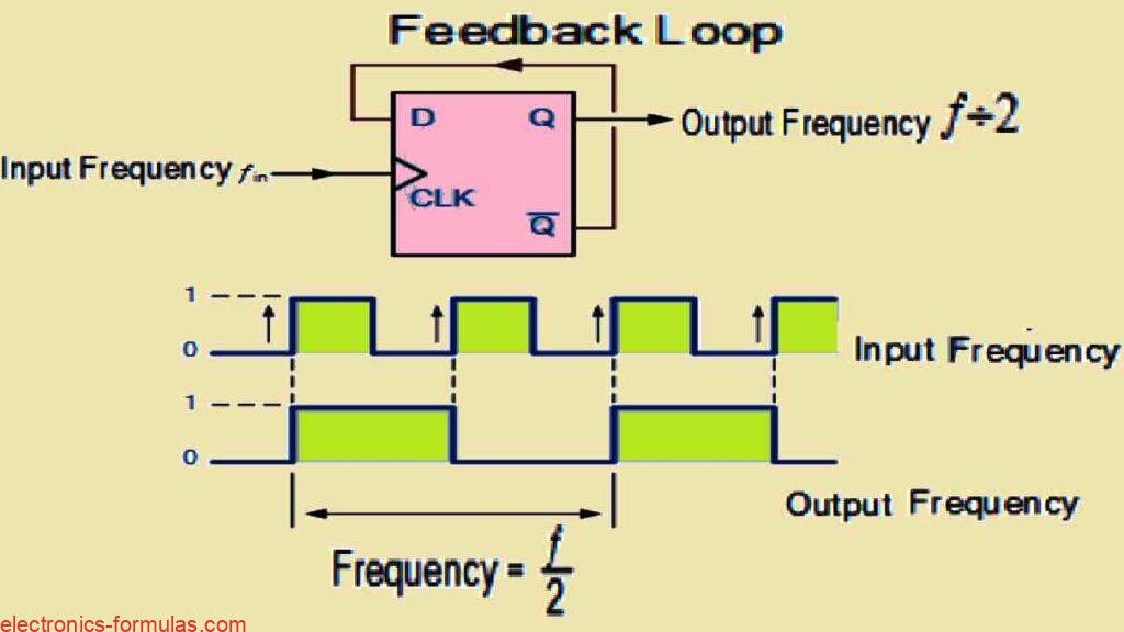
The waveforms shown above clearly demonstrate that when we use a feedback system where the output from Q goes back to the input D, the output pulses at Q have a frequency that is exactly half of the input clock signals frequency (ƒ ÷ 2).
In simpler terms we can say that this circuit is doing Frequency Division, by cutting the input frequency down by half which is also known as an octave.
This setup leads to a special kind of counter called a “ripple counter.” In ripple counters the first clock pulse turns on the first flip-flop and then the output from that flip-flop triggers the next one.
This chain reaction keeps going, with each flip-flop activating the next one in line, creating a rippling effect of the timing signal as it moves through the series of flip-flops which is how they got their unique name.
What’s a Toggle Flip-Flop
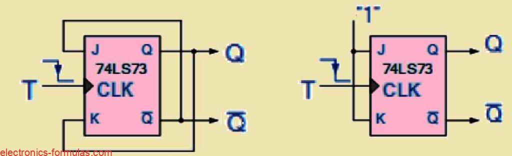
A different kind of digital device that helps with frequency division is called the T-type or Toggle flip-flop. You can make a Toggle flip-flop by making a small change to a regular JK flip-flop.
You can build Toggle flip-flops using D-type flip-flops, like we talked about before or you can get them from standard JK flip-flops like the 74LS73 model. This design results in a device that has just two inputs: the main “Toggle” input and the negatively controlled “Clock” input as illustrated in the following sections:
Working Concept of the IC 74LS73 Toggle Flip Flop

A “Toggle flip-flop” is designed to easily switch back and forth between two different states, which are the “toggle state” and the “memory state,” hence it is called the “Toggle flip-flop” Because it only has these two states, the T-type flip-flop is really good for things like dividing frequencies and making binary counters.
When building binary ripple counters you can use “Toggle” or “T-type flip-flops” by connecting the output of one flip-flop to the clock input of the next one.
The way toggle flip-flops are designed makes them perfect for ripple counters because they change from one state to another—either from HIGH to LOW or from LOW to HIGH—every time the clock ticks.
This feature makes it easy to create the frequency divider and the ripple counter circuits using regular T-type flip-flop setups.
If you connect two T-type flip-flops in a row, then first flip-flop divides the input frequency by two (ƒ ÷ 2), and then the second flip-flop divides it by two again.
This means that output frequency is now one quarter of the original clock frequency which can be shown as (ƒ ÷ 4).
When you add more toggle or “T-type” flip-flops to a chain, then output clock frequency gets lower, basically being cut in half each time. This keeps happening so you can think of the output frequency as 2 raised to the power of “n,” where “n” is the total number of flip-flops used in the setup.
The Toggle or T-type flip-flop is a special device that divides the frequency by two. It works similarly to the regular JK-type flip-flop and is triggered by the rising edge of the clock signal.
This means that each bit shifts to the right by one flip-flop position. Plus all the flip-flops can be reset at any time and can change their state based on either the leading or trailing edge of the clock signal, making them great for dividing frequencies.
This type of counter circuit which is used for frequency division, is known as an Asynchronous 3-bit Binary Counter. The output which goes from QA to QC has three bits and counts in binary from 0 to 7 with each clock pulse.
In an asynchronous counter, the clock signal only goes to the first flip-flop and then the output from that flip-flop acts as the clock signal for the next one. This means that each stage gets its clock signal from the one before it causing the clock pulse to become halved at every stage of the counter.
This type of setup is often called as Asynchronous because each clock event happens on its own which means that bits in the counter do not change at the same time.
The counter counts up in order, starting from 0 and going to 7. This kind of counter is usually known as an “up” or “forward” counter (CTU) and it can also be called a “3-bit Asynchronous Up Counter.”
The three-bit asynchronous counter shown is an example of this type and uses flip-flops that work in toggle mode. There are also Asynchronous “Down” counters (CTD) that we can used.
Truth Table for a 3-bit Asynchronous Up Counter
| Clock Cycle | Output Bit Pattern | ||
| QC | QB | QA | |
| 0 | 0 | 0 | 0 |
| 1 | 0 | 0 | 1 |
| 2 | 0 | 1 | 0 |
| 3 | 0 | 1 | 1 |
| 4 | 1 | 0 | 0 |
| 5 | 1 | 0 | 1 |
| 6 | 1 | 1 | 0 |
| 7 | 1 | 1 | 1 |
The D-type flip-flop produces an output that runs at a frequency that is exactly half of the input signal. This means that it counts in twos.
By connecting more D-type or Toggle Flip-Flops together you can create circuits that divide the input clock frequency by 2, 4, 8, and so on. This allows you to build a binary counter circuit that can divide by any power of two.
Understanding Frequency Division with Binary Counters
A counter is like a special type of register or pattern maker. When it gets an input pulse called the “Clock,” it creates a specific output pattern or sequence of binary values. The clock signal is super important for moving data around in these systems.
Usually counters are logic circuits that can either add or subtract one from a count. But when they are set up as asynchronous divide-by-n counters then they can take incoming pulse signals and create a divided clock signal.
Counters are made by connecting flip-flops together and you can link as many flip-flops as you want to make a “divide-by-n” binary counter. Here “n” is the number of stages in the counter which is often called the Modulus. The modulus or “MOD” tells you how many output states the counter goes through before it starts over at zero, completing one full cycle.
For example a counter with three flip-flops will count from 0 to 7 which is 2^n – 1. This means it has eight different output states that show the decimal numbers from 0 to 7 so we call it a Modulo-8 or MOD-8 counter. Likewise a counter with four flip-flops counts from 0 to 15 making it a Modulo-16 counter, and then this pattern keeps going.
You may look at the following example to understand the situation:.
- 3-bit Binary Counter = 23 = 8 (modulo-8 or MOD-8)
- 4-bit Binary Counter = 24 = 16 (modulo-16 or MOD-16)
- 8-bit Binary Counter = 28 = 256 (modulo-256 or MOD-256)…..and we can continue this way…
Additional flip-flops could be added to the counter in order to raise the modulo number, and cascading is one way to create higher modulus counters. The modulo or MOD number may thus be expressed easily as follows:
MOD number = 2n
Understanding 4-bit Modulo-16 Counter


Asynchronous Counters that use multiple bits and are connected in this way are often called “Ripple Counters” or ripple dividers.
This name comes from how the change in state at each stage seems to move or “ripple” through the whole counter, starting from the least significant bit (LSB) and going to the most significant bit (MSB).
You can find ripple counters as standard integrated circuits (ICs) like the 74LS393 which is a dual 4-bit counter, or the 74HC4060, a more advanced 14-bit ripple counter that has a built-in clock oscillator.
These devices are really good at dividing the fundamental frequency effectively.
Conclusions
When we talk of frequency division, the toggle mode flip-flops are used in a series to create a counter that cuts the input frequency in half.
One flip-flop can reduce the clock frequency known as ƒIN, to half of what it was originally. When you connect two flip-flops together then the frequency drops to one-fourth of ƒIN and this pattern keeps going with more flip-flops, each one halving the frequency again.
A cool thing about using toggle flip-flops for this is that the output signal at each stage has a perfect 50% duty cycle which means the waveform is balanced.
The final output clock signal from this setup will have a frequency that matches the input clock frequency divided by the MOD number of the counter, which is why we call these circuits “divide-by-n” counters. These counters are made by linking individual flip-flops and can be sorted based on how they are clocked.
For Asynchronous counters which are also known ripple counters, we see that the first flip-flop is triggered by an external clock pulse and each following flip-flop is activated by the output of the one before it. On the other hand Synchronous counters are set up so that the clock input goes to all flip-flops at the same time, letting them to be clocked together.
References: