
The basic LC Oscillator tank circuit that we discussed in one of our earlier posts has a significant limitation: it cannot alter the magnitude of its output oscillations. This means that the oscillations might be either too large or too little, making it difficult to get the desired results. It might also be difficult for the user to fine-tune the oscillator to the required operating frequency.
Also we have to make to sure that the electromagnetic coupling between L1 and L2 is set precisely and correctly, or else the oscillations will fade out or become distorted. So, this can make it difficult for the user to obtain stable oscillatory amplitudes.
However, there is a way to solve this, it is by employing a regenerative feedback, through which we can maintain a regular and constant oscillations output from the circuit. We can accomplish this by carefully adjusting the feedback voltage that is supplied back into the circuit. If the oscillations get too large, we cut the amplifier’s gain to bring them down, on the other hand if the gain gets too small, we raise the gain to push the oscillations higher. This technique which is known as Automatic Base Bias helps to maintain the oscillations stability and makes it constant.
One of the most notable advantages of Automatic Base Bias is the ability to apply Class-B or Class-C biasing conditions in the BJT circuit, which means it enables for more efficient oscillator operation. We are able to implement this by limiting the collector current so that it only conducts during particular periods of the oscillation cycle and thus reducing the quiescent collector current of the BJT to minimal levels.
This “self-tuning” base oscillator circuit which includes the above explained Automatic Base Bias, is a common LC parallel resonant feedback oscillator arrangement which is also known as the Hartley Oscillator.
What is LC Circuit in a Hartley Oscillator

In the Hartley Oscillator we have a special kind of circuit called an LC circuit (which uses inductance and capacitance to tune a frequency) which is connected between the collector and base of a BJT transistor amplifier. Here, the emitter of the BJT is connected to one specific point on the LC coil (inductor) in order to trigger an oscillating voltage output.
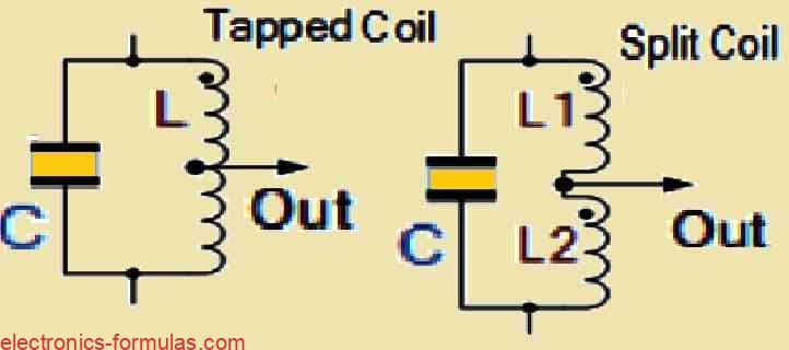
Looking at the feedback part of the tuned tank LC circuit we find that it is taken from the center tap of the inductor coil, or these coils can be two separate coils in series which are in parallel with a variable capacitor C.
The Hartley circuit is often also referred to as a split-inductance oscillator because the coil L it employs is a center-tapped type of coil. In actuality, the inductance of this coil L acts like two separate coils in very close proximity with the current flowing through coil section XY inducing a current into the lower coil section of YZ.
Furthermore, in a Hartley Oscillator configuration it is possible for us to provide the feedback voltage through a couple of coils which can be created in different ways such as, either by a single coil tapped at the center (similar to an autotransformer) or using a pair of coils connected in series and configured in parallel with a single capacitor (C) as shown below.
Understanding a Basic Hartley Oscillator Circuit Design

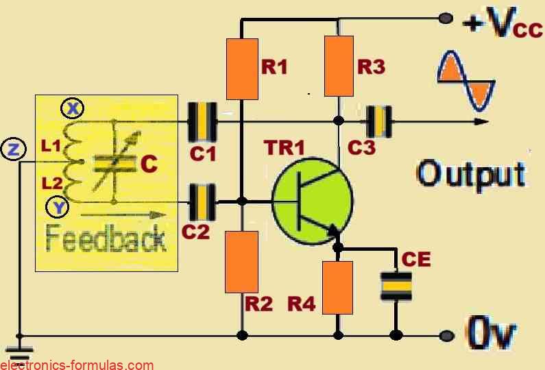
Referring to the above circuit, as soon as the circuit reaches a state of oscillation, the voltage at point X (collector) exhibits a 180-degree phase shift relative to the voltage at point Y (emitter) and with respect to the voltage at point Z (base). Since the impedance of the load connected at the collector of the BJT is completely resistive at the oscillation frequency, so an increase in the base voltage naturally causes a corresponding drop in the collector voltage.
Therefore the voltage between the Base and Collector of the transistor shifts by 180 degrees. This happens because of the byproduct of the inherent oscillation of the circuit, and this phase shift is what exactly enables the positive feedbacks to sustain the circuits oscillations. The feedback loop’s initial 180-degree phase shift in conjunction with this 180-degree phase shift together creates the perfect scenario required for the positive feedback to sustain the oscillations.
The precise positioning of the inductor’s “tapping point” determines how much feedback happens in this circuit. The more we push this point toward the Collector, the more feedback it generates while conversely, the more we move this point away from the Collector, the less feedback there is. On the other hand we find that there is a decrease in the feedback level if the output voltage taken between the Collector and the earth is increased and vice versa. In this configuration the BJT transistor is normally DC biased by the resistors R1 and R2, which keeps it functioning throughout a uniform and a predictable range.
In this Hartley Oscillator arrangement, the DC Collector current of the transistor flows through a portion of the coil and because of this reason this configuration is referred to as “Series-fed”. The combination of these elements makes it possible for the coil and collector to produce the output power efficiently, and also allows the circuit to continue oscillating at the specific calculated frequency.
To calculate the oscillation frequency of an Hartley Oscillator we can use the following formula:
f = 1/2π√(LTC)
In the above formula LT = L1 + L2 + 2M
It is important to keep in mind that the total cumulatively coupled inductance abbreviated as LT in the above formula, includes the mutual inductance “M” between the two independently wound coils whenever a configuration like this is used. This is a significant consideration to take into account while analyzing the overall behavior of the oscillator circuit.
If you want you can easily tweak and adjust the frequency of oscillations simply by changing the value of the “tuning” capacitor C this can be also done by adjusting the position of the iron-dust core within the coil, and this process is known as the inductive tuning. This dual method of adjusting the output frequency allows the Hartley Oscillator to provide an output across a wide frequency range, making the tuning process surprisingly simple. Furthermore the Hartley Oscillator maintains a steady output amplitude across its full frequency range, making it a very dependable and predictable oscillator design.
Apart from series-fed Hartley oscillator design which we discussed earlier, this tuned tank circuit could be further configured like a shunt-fed oscillator, as shown below. This alternate configuration provides us with another feasible method for constructing the Hartley Oscillator circuit, which allows the users to tailor their design to any desired specific requirements or applications.
Understanding a Shunt-fed Hartley Oscillator Circuit

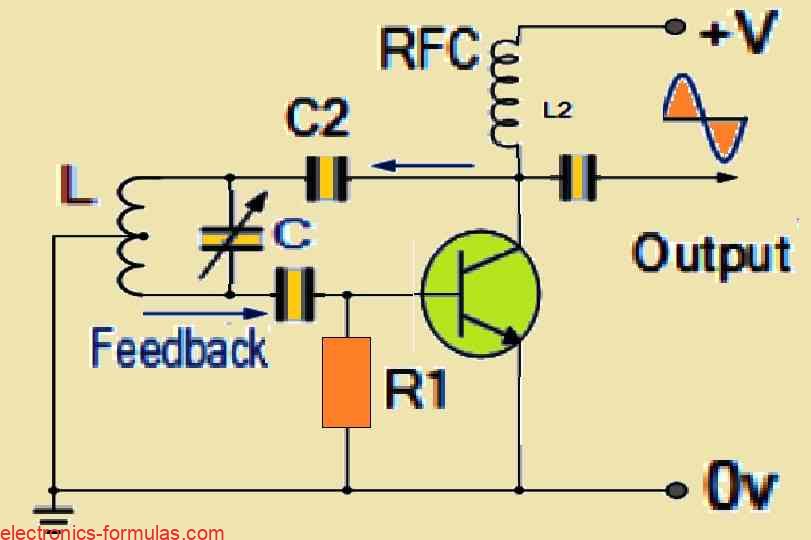
In the shunt-fed circuit concept, it can be observed that both the alternating current (AC) and direct current (DC) components of the BJT collector current take independent pathways all through the circuit, allowing for the separation of these currents. The capacitor C2 effectively blocks the DC component, preventing DC from flowing through the inductive coil L thereby decreasing power waste in the tuned circuit.
The Radio Frequency Coil (RFC) designated as L2 works like a high-reactance component at the frequency of oscillations which diverts almost all of the Radio Frequency (RF) current to the LC tuning tank circuit via capacitor C2. At the same time, the DC component of the circuit travels through L2 to the power supply, unaffected by the impedance of the RFC. It is important to note that a resistor could potentially be used instead of the RFC coil L2, but this would most likely result in a less efficient circuit.
Solving a Hartley Oscillator Circuit Problem
A Hartley Oscillator circuit is designed by the incorporation of two separate inductors, each measuring 0.6 millihenries (mH) in value, and is intended to resonate in parallel with a variable capacitor that can be varied between 47 and 470 picofarads (pF). The main objective is to calculate the upper and the lower frequencies of oscillation, and to also determine the bandwidth of the Hartley oscillator.
To begin with, we first calculate the frequency of oscillation of the circuit:
fr = 1/2π√(LTC)
As per the design we have two inductive coils in series in the circuit, so we can calculate the total inductance of the coils in the following manner:
LT = L1 + L2 = 0.6 + 0.6 = 1.2 mH
So now we can calculate the upper frequency of oscillation as given below:
fH = 1/2π√(1.2 * 47)
= 1/6.283√(0.564 * 10-13)
= 670183 Hz = 670.183 kHz
Likewise, next we calculate the lower frequency of oscillation as given below:
fL = 1/2π√(1.2 * 470)
= 1/6.283√(5.64 * 10-13)
= 211930 Hz = 211.930 kHz
Lastly, we calculate the bandwidth of the Hartley Oscillator, in the following manner:
Bandwidth = fH – fL
= 670 – 212 = 458 kHz
How an Hartley Oscillator using an Op-amp Works
Apart from using a bipolar junction transistor (BJT) as the amplification stage of the Hartley oscillator’s design, it is also possible to use an operational amplifier (op-amp) or a field-effect transistor (FET). The functionality of an op-amp Hartley oscillator is the same as that of its transistorized counterpart and the frequency of operation of this op-amp circuit could be calculated in the same way as the transistor-based version. Please keep in mind that the circuit design shown below depicts one possible configuration for this oscillator.

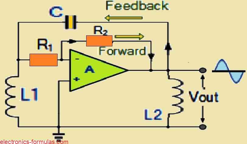
The primary benefit of creating a Hartley oscillator with an operational amplifier as the active element is that the feedback resistors R1 and R2 allow the gain of the op-amp to be easily adjusted. Similar to the previously discussed transistorized oscillator, the gain of this circuit must be equal to or slightly higher than the ratio of inductance L1 to L2. But if the two inductive coils are mounted onto the same core, which results in a mutual inductance M across these coils, then the ratio of the two becomes a more complicated one, specifically (L1+M)/(L2+M), and this variable must be carefully taken into account while designing and optimizing the oscillator.
Conclusions
Finally, we can conclude that the Hartley Oscillator is basically a parallel LC resonator circuit which uses an inductive divider to achieve the required feedback. We can implement this inductive divider through a single tapped coil or also through two separate independent coils. Just like most of the other LC oscillators concepts, the Hartley oscillator also comes in various different forms, but the most common type of Hartley oscillator circuit is the one which uses the transistor circuit configuration.
In this transistorized configuration, the tank circuit is tuned to a specific resonant frequency by feeding a fraction of the output signal back into the emitter terminal of the transistor through a tapped coil. Because of the fact that the emitter output of the BJT is always in-phase with the collector output of the BJT, this feedback signal will be always positive. Then the frequency of oscillation for this configuration which will be a sine-wave voltage, can be determined by using the resonance frequency data of the tank circuit.
The next upcoming tutorial that I would be discussing with you will again deal with the oscillator circuits, in which we will investigate an another type of LC oscillator circuit which works in just the opposite way to the Hartley oscillator, and the name of this oscillator concept is the Colpitts Oscillator. Unlike the Hartley oscillator circuits which relies on an inductive divider for its operations, the Colpitts oscillator works with two capacitors in series to create a center-tapped capacitance in parallel with a single inductance within its resonant tank circuit, we will discuss more on this in the next chapter.
References: Hartley oscillator