The second of Gustav Kirchhoff’s essential rules that we may apply to circuit analysis is the voltage law. According to his voltage law, the algebraic total of all the voltages around any closed loop in a circuit is equal to zero for a closed loop series route. This is due to the fact that a circuit loop has a closed conducting route which prevents energy loss.
That is to say, ΣV = 0, which is the algebraic total of ALL the potential differences around the loop. The phrase “algebraic sum” here refers to accounting for the signs and polarity of the sources and voltage drops along the loop.
Since traveling around a closed loop, or circuit, will return you to the beginning potential of the circuit and prevent any loss of voltage, this Kirchhoff concept is also known as the Conservation of Energy. As a result, any voltage drops that occur along the loop must be equivalent to any voltage sources came across.
Thus, in order to ensure accurate calculations when applying Kirchhoff’s voltage law to a particular circuit element, we must pay careful consideration to the algebraic signs (+ and –) of the voltage drops across components and the emfs of sources.
We’ll first examine Kirchhoff’s voltage law (KVL) in greater detail by first understanding the voltage drop across an individual component, which is a resistor.
A Single Circuit Component (Resistor)
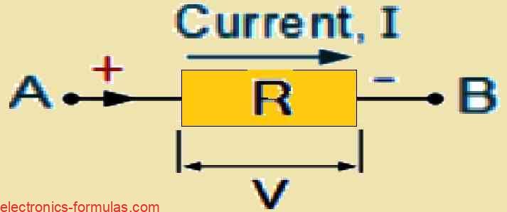
As is customary with conventional current flow we assume that current (I) in this circuit flows with a positive charge.
A voltage drop of -IR occurs across a resistor when current flows through it from the high potential point (A) to the lower potential point (B).
When the current is reversed (from B to A), the voltage rises by +IR because the movement is opposing the current and occurs from low potential to high potential.
It is essential to take into account both the polarity of the components and the direction of current flow in order to correctly use Kirchhoff’s Voltage Law (KVL). There is a voltage drop when going in the same direction as the current through a resistor. A voltage rise, on the other hand, results from an emf source.
Selecting a reference direction for the current flow around the closed loop, clockwise or counterclockwise, is necessary when using KVL. The final answer will still be legitimate even if the chosen direction deviates from the actual current flow, possibly with a negative sign to compensate for the discrepancy.
Let us examine a single loop circuit and confirm KVLs validity to further reinforce this idea.
Analysis of a Single-Loop Circuit using KVL
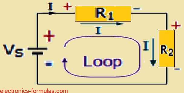
According to Kirchhoff’s voltage law, any loop’s algebraic sum of potential differences has to be zero, or ΣV = 0. All two resistors (R1 and R2) must have an identical current flowing across them because they are connected in series and form a single loop.
As a result, KVL provides the voltage drop across resistors R1 = IR1 and R2 = IR2, respectively, as can be seen in the below calculations.
VS + (-IR1) + (-IR2) = 0
∴ VS = IR1 + IR2
VS = I(R1 + R2)
VS = IRT
Where: RT = R1 + R2
It is clear that using Kirchhoff’s Voltage Law on this one closed loop yields the calculation for the series circuit’s equivalent or total resistance. We may proceed to build on this to get the values of the voltage drops surrounding the loop.
RT = R1 + R2
I = VS / RT = VS / (R1 + R2)
VR1 = IR1 = VS [R1 / (R1 + R2)]
VR2 = IR2 = VS [R2 / (R1 + R2)]
Solving a Kirchhoff’s Voltage Law Problem
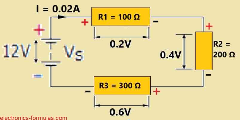
Consider a series circuit consisting of three resistors: R1 = 100 Ω, R2 = 200 Ω, and R3 = 300 Ω. The circuit is powered by an ideal 12 V DC battery. Determine the following:
a) Total resistance of the circuit.
b) Current (I) flowing through the circuit.
c) Current through each resistor (since they are in series, it will be the same).
d) Voltage drop across each resistor.
e) Verify Kirchhoff’s Voltage Law (KVL) for this circuit.
Solution:
a) Total Resistance (RT)
RT = R1 + R2 + R3 = 100 Ω + 200 Ω + 300 Ω = 600 Ω
Then the total circuit resistance RT is equal to 600 Ω
b) Circuit Current (I)
I = VS / RT
= 12 / 600
= 0.02 Amp
The entire circuit current, I, is thus 200mA, or 0.2 amperes.
c) Current Flowing across Each of the Resistors
Since the resistors are connected in series and form a single loop, they all receive the same amount of current. Therefore:
IR1 = IR2 = IR3 = ISERIES = 0.02 amperes
d) Voltage Drop Across Each Resistor
VR1 = I x R1 = 0.02 x 10 = 0.2 volts
VR2 = I x R2 = 0.02 x 20 = 0.4 volts
VR3 = I x R3 = 0.02 x 30 = 0.6 volts
e) Verifying Kirchhoff’s Voltage Law (KVL):
VS + (-IR1) + (-IR2) + (-IR3) = 0
12 + (-0.02 * 100) + (0.02 * 200) + (-0.02 * 300) = 0
12 + (-2) + (-4) + (-6) = 0
∴ 12 – 2 – 4 – 6 = 0
Kirchhoff’s Voltage Law (KVL) is satisfied in this circuit, because he algebraic sum of the voltage drops around the closed loop equals zero, and this confirms the principle of conservation of energy.
Kirchhoff’s Circuit Loop
Kirchhoff’s Voltage Law (KVL), the second of his fundamental circuit analysis laws, says that the algebraic sum of all voltage drops around a closed loop is zero.
This summing starts and ends at the same point (ΣV = 0), taking into account the voltage polarity throughout the loop. KVL represents the principle of energy conservation within a closed circuit.
Because the law controls the voltage distribution in series circuits, its usefulness is very clear. Considering series circuits are by nature voltage dividers, KVL is an essential tool for circuit analysis and design.
References: Kirchhoff’s Voltage Law (KVL)
Leave a Reply