In the earlier lessons we had about transformers, we kind of assumed that these devices were flawless.
This means we thought their windings did not experience any core losses or copper losses at all.
But when we actually use a transformer “on-load” we have to face the reality that there are always going to be some losses associated with loading in real-world transformers.
Now you might be wondering what exactly does “Transformer Loading” mean?
To get a clearer picture let us investigate into what happens to a transformer when it is in the “no-load” condition.
This is the state where its secondary winding is not connected to any electrical load which means there is no current flowing through the secondary side at all.
Now what happens when we have the secondary side winding of a transformer is open-circuited? This basically means that nothing is plugged into it and the transformer is not loaded at all.
In this situation we say that the transformer is on what we call “no-load.” Now when we connect the primary winding of this transformer to an AC sinusoidal supply the presence of that primary supply voltage actually causes a small current IOPEN to flow through the primary coil winding.
Now this thing called the back EMF (electromotive force) along with the resistance of the primary winding work together to limit how much of this primary current can flow while the secondary circuit remains open and disconnected.
It is like putting a governor on a car to keep it from going too fast. Naturally this no-load primary current (which we call Io) has to be sufficiently high so that it can maintain a strong enough magnetic field.
Take a look at the circuit below.
Transformer without a Load (“No-Load”)

So even though we have the secondary circuit just hanging out open and not connected to anything, the ammeter we see up there is still going to show that there is a tiny bit of current flowing through the main winding.
Now this no-load main current can actually be broken down into two distinct parts which we can think of like two halves working together:
First we have IE, which is what we call an in-phase current. This part of the current is responsible for covering the core losses that happen in the transformer, specifically the hysteresis loss and the eddy current loss.
Then we have another little current called IM. This current is interesting because it creates a magnetic flux that is at a 90-degree angle to the voltage.
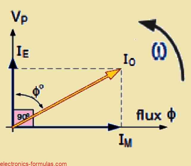
IE = IO * cosφ

IM = IO * sinφ

IO = √(IM2 + IE2)
Let us remember that when we talk about the transformer’s typical full-load current, it is actually much larger than this no-load main current which we refer to as Io.
Now there will be a slight variation in the phase angle. This is because Io does not lag behind the supply voltage which we call Vp, by exactly 90 degrees.
In fact we can say that cosφ = 0 because of the 90 degrees lag, but there are some other factors at play too.
This phase angle variation is also influenced by those iron losses that occur in the core of the transformer, as well as a tiny bit of copper losses that happen in the primary winding.
Solving a Transformer Loading Problem #1
Let us consider a single-phase transformer that has two important components. First we have the energy component IE and in this case it is measured at 2.5 Amps.
Then we also have the magnetizing component IM measured at 5.5 Amps.
Now we want calculate the no-load current Io and we also want to find out the resulting power factor from these values.
To calculate the no-load current Io we can use a formula that combines these two components. The formula looks like this:
Io = √(IE2 + IM2)
So if we put in our values for IE and IM into this formula it would look like this:
Io = √(2.52 +5.52)

Io = √(6.25 + 30.25)

Io = √(36.5)

Io ≈ 6.04 Amps
Now that we have calculated the no-load current Io to be approximately 6.04 Amps we also want to determine the power factor. The power factor can be calculated using the following formula:
Power Factor (PF) = IE / Io
So if we substitute our values into this equation it would be:
PF = 2.5 / 6.04
PF ≈ 0.41
Transformer with a Load (“On-Load”)
When you connect an electrical load to the secondary winding of a transformer it causes the transformer to work and current starts to flow through the secondary winding to the load.
This current flows because of the secondary voltage that is created by the magnetic flux from the primary current in the transformer’s core.
The secondary current IS depends on what the load is like and it creates its own magnetic field ΦS in the transformer core.
This new magnetic field goes in the opposite direction of the main magnetic field ΦP created by the primary winding.
Because these two magnetic fields push against each other the overall magnetic field becomes weaker than the magnetic field produced by the primary winding when the secondary circuit was not connected.
The magnetic fields from both sides work together to lower the back EMF in the primary winding which makes the primary current IP go up a little bit.
The primary current keeps rising until the magnetic field in the core returns to its original strength.
For a transformer to work properly the magnetic fields on the primary and secondary sides need to be balanced.
This balance ensures that the power is equal on both sides.
Let us take a look at the circuit below.
Circuit Diagram Depicting Transformer “On-load”
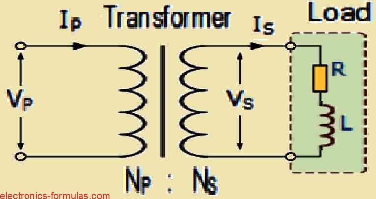
The turns ratio of a transformer tells us that the voltage created in each winding depends on how many turns are in that winding.
Also the power that comes out of a transformer is the same as the power that goes in which can be calculated by multiplying volts by amperes (V x I). So we can say that:
- PowerPrim = PowerSec
- VP * IP = VS * IS
- ∴ VP/VS = IS/IP
Transformer Ratio
We already learned that the voltage ratio of a transformer is the same as its turns ratio which means “voltage ratio = turns ratio.”
This means that we can connect the voltage, current, and number of turns in a transformer and it can be expressed like this:
n = NP/NS = VP/VS = IS/IPWhere:
NP/NS = VP/VS indicates the ratio of voltage
NP/NS = IS/IP signifies the ratio of current.Remember that the current in a transformer is inversely proportionally to both the voltage and the number of turns. When you have a load on the secondary winding and if you increase the voltage then the current has to decrease to keep the power balanced.
On the other hand if you decrease the voltage then the current has to increase. So you can think of it like this “higher voltage means lower current” and “lower voltage means higher current.”
The transformer ratio shows how the number of turns in the primary and secondary windings relate to the voltage and current in each winding.
We can use this relationship to calculate any unknown values like voltage (V), current (I), or the number of turns (N) by rearranging our previous transformer ratio equation.
Vp = (Vs * Np)/Ns = (Vs * Is)/Ip
Vs = (Vp * Ns)/Np = (Vp * Ip)/Is
Np = (Vp * Ns)/Np = (Ns * Is)/Ip
Ns = (Vs * Np)/Vp = (Np * Ip)/Is
Ip = (Vs * Is)/Vp = (Ns * Is)/Np
Is = (Vp * Ip)/Vs = (Np * Ip)/Ns
The total current taken from the power source by the primary winding is the vector sum of the no-load current Io and the extra current I1 that comes from the load on the secondary transformer. This extra current lags behind the supply voltage by an angle of Φ.
We can illustrate this relationship through the following phasor diagram.
Phasor Diagram Illustrating the Transformer Loading Current
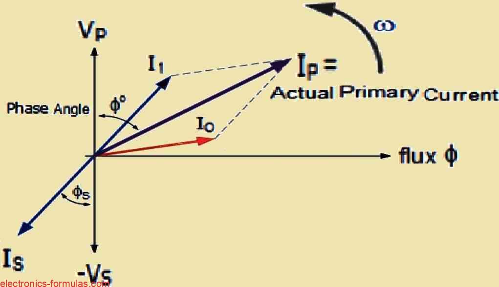
We can use the below given methods to find the primary current IP by looking at the currents IS and Io.
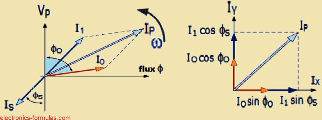
Horizontal Component, Ix = Io * sinφo + I1 * sinφs

Vertical Component, Iy = Io * cosφo + I1 * cosφs

∴ Ip = √(Ix2 + Iy2)

and p.f. = cosφ = Iy / Ip
Solving a Transformer Load Problem #2
Let us consider this single phase transformer that has a total of 1200 turns on its primary winding and then it has 220 turns on its secondary winding.
Now when the transformer is not under any load it draws a current of 4 Amps from the supply and this current has a power factor of 0.2 lagging which is kind of low.
Now our task is to calculate the primary winding current which we will call IP. We also want to calculate the corresponding power factor φ, when the transformer is actually supplying a load. In this case the secondary current that the transformer is providing to the load is 300 Amperes and it has a power factor of 0.8 lagging.
Np / Ns = Is / Ip ∴ I1 = Ns × Is / Np = 220 × 300 / 1000 = 66 A

ϕo = cos⁻¹(0.2) = 78.5°
ϕs = cos⁻¹(0.8) = 36.8°

Ix = Io sin ϕo + I1 sin ϕs
Ix = 4 × sin(78.5) + 66 × sin(36.8)
Ix = 43.45 A

Iy = Io cos ϕo + I1 cos ϕs
Iy = 4 × cos(78.5) + 66 × cos(36.8)
Iy = 53.64 A

Ip = √(Ix² + Iy²)
Ip = √(43.45² + 53.64²)
Ip = 69.03 A

p.f. = cos ϕ = Iy / Ip = 53.64 / 69.03 = 0.77 = 39.1°
So we might have noticed that the phase angle of the primary current which we refer to as φP is pretty much identical to the phase angle of the secondary current which we call φS.
This similarity happens because the no-load current which is about 4 amperes is really tiny when we compare it to the much larger 66 amperes that the primary winding pulls from the supply.
Now when we look at transformers in real life it is important to remember that their windings actually have impedances that include both XL and R.
We really need to consider these impedances when we are drawing phasor diagrams because these internal impedances lead to voltage drops happening within the windings of the transformer.
These internal impedances come from two main sources, first there is the resistance of the windings and second, there is this inductance drop that we call leakage reactance which results from something known as leakage flux.
So overall these internal impedances of the transformer can be expressed as shown in the following image:
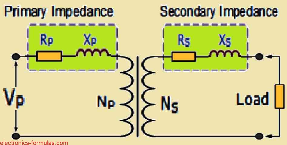
The primary and secondary windings of a transformer have both resistance and reactance which are important characteristics.
In some cases it can actually be pretty helpful to gather all those impedance values on just one side of the transformer. This makes our math calculations a whole lot easier.
Now we can totally move the primary impedances over to the secondary side or we can do it the other way around too.
When we combine those resistance values along with the inductive reactance values we get what are known as “Referred Impedances” or sometimes people call them “Reflected Values.”
The whole idea behind this is to bring together all the impedances inside the transformer so that we end up with just one single referred value for both resistance and inductive reactance.
This value can then be used for either the primary side or the secondary side when we are doing our calculations.
It really simplifies things as you can see in the calculations provided below:
How to Combine Transformer Impedances to Simplify Calculations
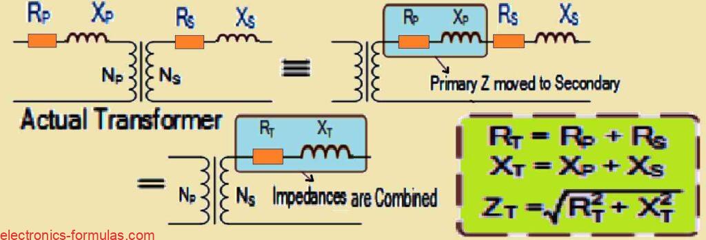
So here is how it works when you want to refer resistance or reactance from one side of a transformer to the other. You need to either multiply or divide by the square of the turns ratio which we write as (Turns Ratio²).
Now when you are reflecting impedances which include both resistance and reactance from the secondary side over to the primary side of the transformer you will want to multiply by the square of the turns ratio which we call N².
On the flip side if you are referring those primary impedances over to the secondary side then you will need to divide by that same square of the turns ratio.
What this means is that when you reflect values from the secondary side back to the primary side you actually end up increasing both resistance and reactance.
But if you are going from the primary side to the secondary side then those values decrease and this is all based on N². This whole concept of impedance reflection applies not just to resistances but also to any load resistance and reactance that is connected to the transformer.
Let us look at an example to make it clearer. Suppose you have a secondary resistance of 3Ω and you want to find out what that would be on the primary side using a turns ratio of 6:1. To calculate the primary resistance you would take 3 and multiply it by 6 squared, which equals 108Ω.
Now if you start with a primary resistance of 4Ω and want to see what that looks like on the secondary side then you would divide 4 by 6 squared. This calculation gives you 0.1111Ω.
Understanding Transformer Voltage Regulation
Now let us talk about what voltage regulation means when we are dealing with transformers.
Basically this concept is all about how the secondary terminal voltage changes when the transformer is under maximum loading conditions which means it is at full load while keeping the primary supply voltage constant.
This regulation is truly important because it shows us how much the voltage drops or sometimes even increases inside the transformer when there is too much load. This can really affect how well the transformer works and its overall efficiency.
When we measure voltage regulation we usually express it as a percentage or in per unit terms compared to the no-load voltage.
So if we say that E represents the no-load secondary voltage and V stands for the full-load secondary voltage we can figure out the percentage regulation of a transformer using a specific calculation as given below:
(No Load – Full Load) / No Load = (E – V) / E * 100%
For example what happens with a transformer that gives us 110 volts when it is not under any load and then drops down to 104.5 volts when it is fully loaded.
This transformer shows a voltage regulation of 5%. The difference we see between the electromotive force which we call E and the voltage which we refer to as V is affected by the internal impedance of the winding.
This impedance includes both its resistance which we label as R and even more importantly its alternating current reactance which we call X along with the current flowing through it and the phase angle.
Now here is something interesting: we notice that voltage regulation tends to go up when the power factor of the load becomes more lagging which means it has an inductive nature.
When we think about how transformers handle loading voltage regulation can show up as either a positive or negative value. This all depends on how we use the no-load voltage as our reference point.
If we see a decrease in regulation as we apply load that is one scenario or if we look at it from the perspective of full-load voltage where we notice an increase in regulation as we take away or reduce the load that is another way to see it.
In general, core-type transformers do not regulate as well as shell-type transformers especially when they are under heavy loading conditions. This difference comes from how well the flux is distributed in shell-type transformers and this is due to how their coil windings are interlaced.
References:
Leave a Reply