The term “inclusive” in “inclusive NOR” simply tells us that it is an alternative way of referring to a regular NOR gate. Like a standard NOR gate, the inclusive NOR gate gives us a logic “1” (high) output when all its inputs are at logic “0” and we get an output logic “0” (low) when any of its input is logic “1”.
Equivalent of Logic NOR Gate

A NOR gate operates by first executing an OR operation on its inputs and then taking of the NOT from the result. To describe its Boolean expression we first start by combining the inputs, A and B, using the OR operation which is written as A+B. However because the NOR gate inverts this result, we apply a NOT operation which is indicated by an overline or a line above the expression ( ‾‾ ), as shown below:
A+B = Q
In simple words, we can describe the function of a NOR gate as: “If both inputs A and B are not true (meaning they are both ‘0’), then the output Q will be true (which is ‘1’).” Conversely it also means that if either input A or B is true (i.e., ‘1’), then the output Q will be false (i.e., ‘0’).
Logic NOR Gate using BJTs
It is quite easy to create a simple 2-input logic NOR gate by configuring RTL Resistor-transistor switches which two BJTs may be connected together through resistors attached directly to the bases of the BJTs forming the inputs. In order to get a positive output at Q, it is necessary that both transistors are in completely switched “OFF” condition.
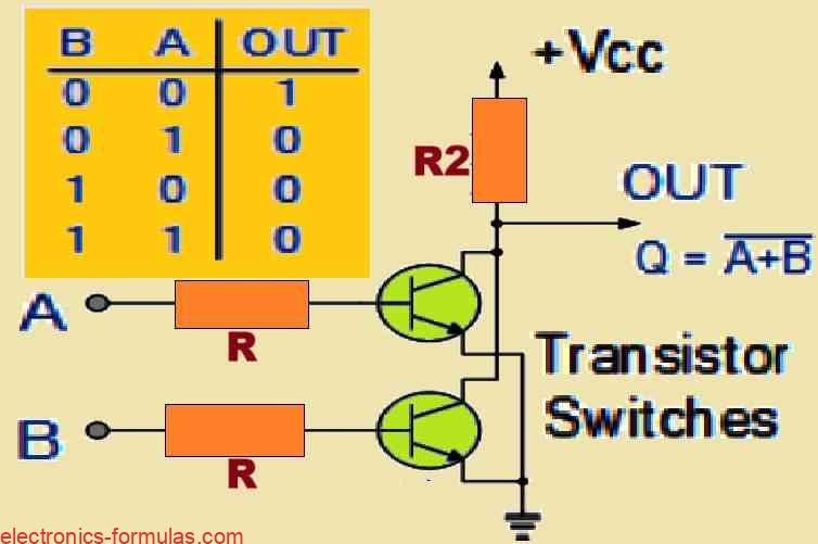
We normally use logic NOR gates by configuring digital circuits, to achieve a specific logical operation. If we look at the symbol of a NOR gate, we find that it looks like a regular OR gate but it carries a small circle, or “inversion bubble,” at the output. This bubble simply tells us that this gate performs a NOT operation in addition to the OR function, meaning it will give you a “HIGH” output of 1 only when both of its inputs are logic “LOW” or 0.
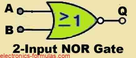
Symbol and Truth Table of the 2-input Logic NOR Gate
Symbol
Truth Table
| B | A | Q |
| 0 | 0 | 1 |
| 0 | 1 | 0 |
| 1 | 0 | 0 |
| 1 | 1 | 0 |
Boolean Expression is Q = A+B, which we can read as A OR B gives NOT Q
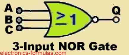
Symbol and Truth Table of the 3-input Logic NOR Gate
Symbol
Truth Table
| 0 | 0 | 0 | 1 |
| 0 | 0 | 1 | 0 |
| 0 | 1 | 0 | 0 |
| 0 | 1 | 1 | 0 |
| 1 | 0 | 0 | 0 |
| 1 | 0 | 1 | 0 |
| 1 | 1 | 0 | 0 |
| 1 | 1 | 1 | 0 |
Boolean Expression is Q = A+B+C, which we can read as A OR B OR C gives NOT Q
Understanding a 4-input NOR Function

We can write the Boolean expression for a 4-input NOR gate as Q = A+B+C+D, which means that the output Q will be 1 only when all of its inputs A, B, C, and D are at logic “0”.
Now suppose you need a NOR gate with an odd number of inputs, you can achieve this by simply attaching the available extra unused inputs of the gate to ground using “pull-down” resistors to keep them at a low (0) level.
Also, the NOR gate function is sometimes referred to as the Pierce Function and is represented by a downward arrow symbol, like this: A↓B
What is “Universal” NOR Gate
Exactly similar to the NAND gate that we learned in our last tutorial, we can categorize a NOR gate as a “Universal” type of gate, because we can easily hook up these gates to each other to create any other desired form of logic gate function.
So basically, by through specific combinations of NOR gates we are able to generate the three basic forms of gate functions, which are AND, OR and NOT function, as indicated through the following diagrams:
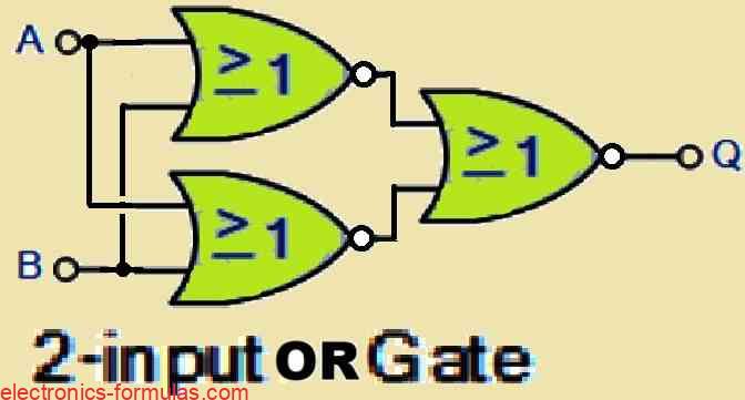

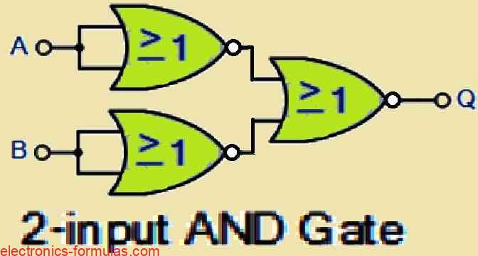
Apart from the above common types of gates, we can further use and combine the NOR gates to create Exclusive-OR, Exclusive-NOR and standard NOR gates.
The following provides the list of the common types digital logic NOR gate IC’s that are readily available in the market:
| Type | Gate | Description |
|---|---|---|
| TTL Logic NOR Gates | 74LS02 | Quad 2-input |
| 74LS27 | Triple 3-input | |
| 74LS260 | Dual 5-input | |
| CMOS Logic NOR Gates | CD4001 | Quad 2-input |
| CD4025 | Triple 3-input | |
| CD4002 | Dual 4-input |
Pinout Diagram of the IC 7402 which is a Common Quad 2-input Logic NOR Gate
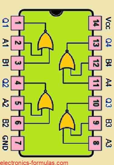
In our next digital logic gate tutorial, I will explain you regarding the digital logic Exclusive-OR gate which are also popularly named as the Ex-OR Gate function. I will also discuss how these logic gates can be implemented in both TTL and CMOS logic circuits, and we will learn about its Boolean Algebra definition and truth tables.
Leave a Reply