The purpose of passive band pass filters is to filter or isolate particular frequencies within a given band. As a result, undesired frequencies outside of the intended range can be attenuated while the right frequencies can flow through selectively. As was previously noted, a non-polarized capacitor and a single series resistor may be used to accurately regulate the cut-off frequency (fc) of a simple RC passive filter. What happens is that a low pass or high pass filter is generated depending on how these components are connected.
Passive filters are utilized in a variety of audio amplifier circuits including pre-amplifier tone controls and crossover filters for speakers. It is frequently required in these applications to pass a certain frequency range that either does not involve DC (0 Hz) or goes up to an exceedingly high frequency limit. Rather, the emphasis is on a certain frequency range which may be wide or narrow.
Cascading for Bandpass Response:
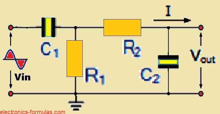
Another kind of passive RC filter may be made by carefully joining (or cascading) a single low pass filter circuit with a high pass filter circuit. The bandpass characteristic of this novel filter arrangement enables the transfer of a selected range or “band” of frequencies which can be narrow or wide. All frequencies outside of this allocated band, are simply attenuated.
This cascaded configuration of passive filters results in a frequency-selective filter known as a band pass filter (BPF).
A Most Common Type of Band Pass Filter Circuit

Band pass filters (BPFs) behave more selectively than high pass filters (which prioritizes high-frequency signals) and low pass filters (which only transmits low-frequency signals). These allows signals that are located inside a certain “band” or “spread” of frequencies to pass through. This selective transmission takes place without creating extra noise or significantly distorting the input signal.
Definition and Measurement of Bandwidth:
The filter’s bandwidth (BW) which is a critical characteristic, is the width of this assigned frequency range. Technically speaking, bandwidth is the range of frequencies that are located between two specific cut-off frequencies (fc). The highest center, or resonant peak, of the filter is 3 dB below these cut-off frequencies. Put more simply.. the bandwidth is the range of frequencies that are purposely reduced or attenuated, whereas signal outside of this range undergo negligible attenuation.
Essential Prerequisite for Effective Operation:
For a working band pass filter, the high pass filter’s cut-off frequency (fcHIGHER) must be lower than the low pass filter’s cut-off frequency (fcLOWER), or simply BW = ƒH – ƒL. This guarantees that the overlapped region of each filter response has the correct range of frequencies.
In the event that this need is not satisfied, the filters will not be able to isolate the intended band, which might cause signal distortion.
The Most Effective Band Pass Filters for Isolating Frequencies:
An “ideal” band pass filter is one that in practice is able to isolate or filter particular frequencies within a given band. Unwanted frequencies outside of the desired range can be eliminated thanks to this focused filtering. Noise cancellation technology, which suppresses a particular noise frequencies, is a well-known example of this feature.
Reactive Components and Second-Order Filters:
Generally speaking, band pass filters are categorized as second-order filters, and sometimes referred to as two-pole filters. They are classified in this way because their circuit design includes two reactive components. Capacitors are commonly used as these reactive parts. In the cascaded circuit, one capacitor is positioned carefully in the low pass filter portion while the other capacitor is located in the high pass filter section.
Integrated Capabilities:
Each of these two filter sections has a capacitor and their combined response produces the overall band pass characteristic. The center frequency and bandwidth of the final band pass filter are determined by the precise arrangement of these filter sections and the values of their individual components.
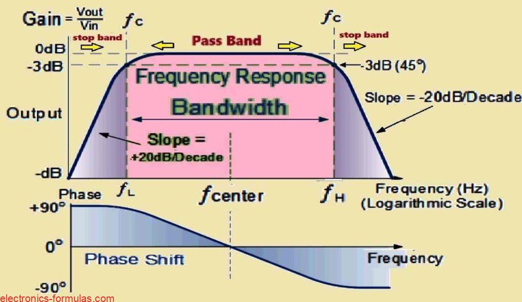
Graph Showing the Frequency Response of a 2nd Order Band Pass Filter

The frequency response characteristics of a band pass filter are clearly seen by the Bode plot diagram shown above. As the frequency drops, the signal weakens and the output voltage rises at a rate of +20 dB/decade, or 6 dB/octave. The frequency will keep rising in this manner until it hits the “lower cut-off point” (fL).
At fL, the output voltage equals 70.7% of the value of the input signal, or -3 dB with respect to the input, represented by 20 * log(Vout/Vin)). This point signifies a major shift in the filter’s response.
Above fL, the output maintains its highest gain (which is also referred to as the “passband”) until it reaches the “upper cut-off point” (fH). This is when the output voltage begins to drop at a rate of -20 dB/decade, or 6 dB/octave, which attenuates any high-frequency signals completely.
The point of highest output gain, also called as the “center frequency” or “resonant peak” (fr), is usually the geometric mean of the two -3 dB points (fL and fH). You can calculate this geometric mean, through the formula fr2 = fH * fL.
Second-Order Filter Classification and Phase Shift:
Band pass filters are classified as second-order filters because they have two reactive components in their circuit architecture. Those reactive components are usually capacitors. Because they are of the second-order, the phase angle that affects the output signal will be twice as prominent as in first-order filters (which experience a single 90° shift). This results in a maximum phase shift of 180° for bandpass filters.
Phase Shift Behavior in Different Frequencies:
Up to the center or resonant frequency (fr), the phase angle of the output signal displays a leading characteristic with regard to the input signal. This lead has a maximum value of +90° at fr, and at this particular frequency, the output and input signals are in phase (0° phase shift). As the frequency exceeds fr and keeps on rising, the phase angle transitions into a lagging behavior, eventually reaching -90° with respect to the input signal.
Finding the Cut-Off Frequency:
The upper and lower cut-off frequencies (fL and fH) for a band pass filter may be calculated using the same formula which is used for calculating low and high pass filters.
The formula is:
fc = 1 / (2πRC) (in Hz),
where: The cutoff frequency is denoted by fc and the mathematical constant π (pi) is roughly equivalent to 3.14159.
The resistance is expressed in Ohms (Ω) by R.
The capacitance in Farads (F) is represented by C.
Please remember that, even with the identical formula, the cut-off frequencies achieved for a band pass filter will be different from those produced for a low pass or high pass filter because of the specific circuit design that was employed to produce the band pass response.
The location of the two cut-off frequency points of the two filters can therefore easily be used to customize the filter’s pass band width.
Solving a Band Pass Filter Problem#1
We want to build a second-order band pass filter using RC components which will allow only the frequencies which are above 2.2kHz and below 25kHz. If the two resistors in the design are 12k, let’s calculate the values of the two capacitors in the design.
Let’s consider the high-pass filter stage first:
The following formula is used to determine the value of the capacitor C1 needed to provide a cut-off frequency fL of 2.2 kHz with a resistor value of 12 kΩ:
C1 = 1 / (2*π*fL*R)
= 1 / (2 * 3.14 * 2200 * 12000) = 6.03 nF
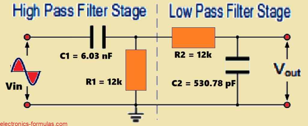
Therefore the values for the resistor R1 and capacitor C1 required for the high-pass filter stage to achieve a cut-off frequency of 2.2kHz will be: R1 = 12kΩ and C1 = 6.03 nF.
Now, let’s consider the low-pass filter stage first:
The below given formula can be used to determine the value of the capacitor C2 to get a cut-off frequency fH of 25 kHz with a resistor value of 12 kΩ:
C2 = 1 / (2*π*fH*R)
= 1 / (2 * 3.14 * 25000 * 12000) = 530.78 pF
So finally, R = 12kΩ and C = 530pF are the values of R2 and C2 needed for the low pass stage to provide a cut-off frequency of 25 kHz.
The Resultant Band Pass Filter Circuit Diagram
Knowing the values of 12kΩ for both resistances R1 and R2, and 6.03nF and 560pF for capacitors C1 and C2 for the high pass and low pass filters respectively, the circuit for our basic passive band pass filter can be drawn as follows.

Now, let’s calculate the cut-off frequencies fL and fH for the above example:
fH = 1 / (2πRC)
= 1 / (2 * π * 12000 * 5.3078556E-10)
= 24987 Hz
fL = 1 / (2 * π * 12000 * 6.03165412e-9)
= 2199 Hz
Calculating the Resonant Frequency or the Center Frequency
Above the cut-off frequencies, band pass filters have a region in which the output signal reaches maximum gain. The region of maximum output, also known as the “resonant frequency” (fr) or the “center frequency,” is the geometric mean of the higher (-3 dB) and lower (-3 dB) cut-off frequencies.
It is critical to understand that the resonant frequency is more than just the arithmetic average (average of the total) of fH and fL. On the contrary, it is calculated applying the geometric mean, that emphasizes the product of the two frequencies.
You can get the geometric mean by using the following formula:
fr2 = fH * fL
Taking the square root of both sides gives us the formula for the resonant frequency:
fr = √(fL * fH)
Now we can substitute the previously achieved values of fL and fH into the above equation to obtain a central resonant frequency as illustrated below:
fr = √(2199 * 24987) = 7412 Hz or 7.41 kHz
Band Pass Filter Response and Practical Considerations
Our previous example provided us with the output frequency response curve for an “ideal” band pass filter. This idealized response assumes that the gain within the passband will be constant and for the stopbands (regions which are outside the desired frequency range) it will be zero.
In a practical scenario where the circuit is built using real components, the actual frequency response of a band pass filter might deviate from this ideal response. This may happen because, the input reactance (opposition to current flow) of the high pass filter circuit can influence the frequency response of the low pass filter circuit, and vice versa, due to their series or parallel connection, which can lead to undesirable effects on the overall performance of the filter.
Addressing Interaction and Isolation:
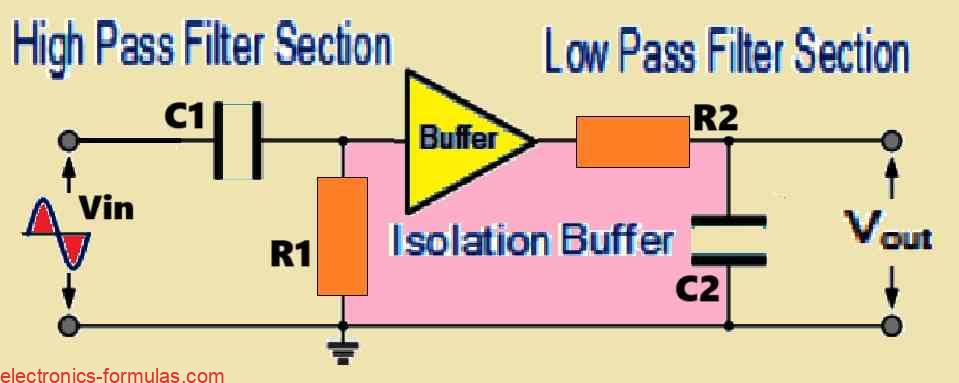
One technique for eliminating this interaction and achieving a more perfect response is to create a electrical isolation between the two individual filter circuits. This isolation may be achieved through a variety of methods as shown in the picture below:

As shown above, an operational amplifier (op-amp) is frequently inserted between these stages to create isolation between them. High input impedance and low output impedance are provided by the op-amp, which functions as a voltage buffer. This arrangement cuts down on the impact of the subsequent stage’s input reactance on the earlier stage’s frequency response.
Conclusion
Cascaded Design:
You can make a basic passive band pass filter by sytematically cascading a single low pass filter along with a high pass filter. Using this combination arrangement will allow you to obtain selective filtering of frequencies inside a specific band.
Bandwidth Definition:
The bandwidth of the filter is measured in Hertz (Hz), and it indicates the frequency range that includes the lower and upper -3 dB cut-off points achieved by the RC arrangement. Depending upon the values of the resistors (R) and capacitors (C) used in the filter circuit, this bandwidth might be very narrow and selective, or wide and non-selective.
Center frequency and phase shift
The center or resonant frequency signifies the geometric mean of the lower and upper cut-off frequencies. The output signal reaches its maximum value and the phase shift between the input and output signals equals zero degrees (0°) at this particular frequency.
Gain and Attenuation:
It is critical to note that the output signals amplitude of a band pass filter, or any passive RC filter for the same reason, will always be less than the input signal amplitude. Passive filters, with a voltage gain of less than one (unity gain), are essentially attenuators. In order to obtain an output signal with a voltage gain higher than unity, the circuit design must include an amplification stage.
Classification of Second Order Filters:
A passive band pass filter is classified as a second-order filter since it has two reactive components, namely capacitors. It is basically made up of two first-order RC filter sections that are cascaded.
Higher-Order Filters:
When you cascade more number of filters stages, the circuit gets transformed into a “nth-order” filter. In this case, the “n” is the total number of individual reactive elements (and therefore poles) in the filter. Examples of this include 2nd-order, 4rth-order, and 10th-order filters, among others. Typically a higher order filter results in a sharper roll-off at a rate of n times -20 dB/decade.
Caution on Capacitor Combination:
It’s crucial to remember that even when multiple independent capacitors are physically joined to generate a single larger capacitance value, the resulting element still continues to be seen as a single capacitor in circuit analysis.
References: How to make a second-order passive bandpass filter?
Leave a Reply