As we already know, a low-pass filter selectively permits signals with frequencies lower than its cutoff frequency fc to pass through. This shows that although the high-frequency elements of the input signal are attenuated (weakened), the lower-frequency elements are retained in the output.
A passive high-pass filter, on the other hand, functions in the opposite way as its name indicates. It mainly allows signals with frequencies higher than its specified cutoff frequency fc, to pass through. Thus only the higher frequencies are allowed to reach the output of this filter, which successfully removes low-frequency components from the input waveform.
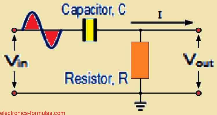
A Simple High Pass Filter Circuit
Frequency Response of a 1st Order High Pass Filter
Since the capacitor in the above circuit configuration has a very high reactance at low frequencies, it functions as an open circuit and prevents any input signals at VIN until the cut-off frequency point (fc) is reached.
As can be seen in the filter response curve below, the capacitor’s reactance has sufficiently decreased above this cut-off frequency point to operate more like a short circuit and enable all of the input signal to flow straight to the output.
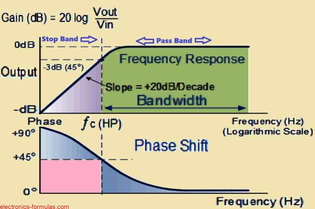
The Bode Plot, also known as the Frequency Response Curve, of a passive high pass filter is an opposite mirror copy of the low pass filter’s response. At low frequencies, the signal becomes attenuated or dampened.
This indicates that the output voltage collapses as the frequency increases. However, once the frequency exceeds the cut-off point (fc), where the resistor’s resistance (R) equals the capacitor’s reactance (Xc), the output voltage begins to rise.
The increase occurs at a rate of +20 decibels each decade (or 6 decibels every octave), and this upward tendency continues until it reaches extremely high frequencies.
It is important to understand that the Bode Plot for a high pass filter extends indefinitely lower in frequency until it reaches the cut-off point (fc). At this particular frequency the output voltage amplitude equals 1/√2 = 70.7% of the input signal magnitude, which corresponds to a -3 dB drop in voltage compared to the input.
Furthermore the phase angle (Φ) of the output signal exhibits a leading behavior compared to the input signal. This means that the output signal reaches its peak slightly before the input signal. Interestingly we find that at the cut-off frequency (fc), the phase lead reaches exactly +45 degrees.
However, while the frequency response curve suggests the filter can transmit all signals indefinitely towards higher frequencies, but this is not entirely true in practice. The real world limitations of the electrical components used ultimately restrict the filter’s effective operating range.
It is worth noting that, the equation used to determine the cut off frequency (fc) for a first-order high pass filter, remains identical to the one used for low pass filters. But the equation for calculating the phase shift requires a slight modification to account for the positive phase angle observed in high pass filters, as shown below.
Formula for Cut-off Frequency and Phase Shift
fc = 1 / 2πRC
Phase Shift Φ = arctan = 1 / 2πfRC
The circuit gain, Av, can be calculated as follows and is expressed as Vout/Vin (quantity):
AV = VOUT / VIN = R / √(R2 + XC2) = R / Z
at low f: XC → ∞, VOUT = 0
at high f: XC → 0, VOUT = VIN
Solving a High Pass Filter Problem Example#1
Find the cut-off, or “breakpoint,” frequency (fc) of a basic passive high pass filter made up of a 100 kΩ resistor coupled in series with an 100 pF capacitor.
We can calculate the cut-off frequency (fc) using the following formula for a first-order RC high pass filter:
fc = 1 / (2πRC)
Now, let us substitute the given values into the formula:
- R = 100,000 Ω (100 kΩ converted to Ohms)
- C = 100 x 10-12 F (100 pF converted to Farads)
Calculate the product of R and C:
- RC = 100,000 Ω * 100 x 10-12 F = 0.00001 seconds
Find now, the reciprocal of 2πRC:
- 1 / (2πRC) = 1 / (2 * 3.14159 * 0.00001 seconds)
Calculate the cut-off frequency (fc):
- fc ≈ 15915.50 Hz (rounded to two decimal places)
Therefore the cut-off frequency (fc) for this simple passive high pass filter will be approximately 15915.50 Hz. This means that the filter will effectively block all signals below 15915.50 Hz and allow all signals above this frequency to pass through.
Understanding Second-order High Pass Filter
Just low pass filters, high pass filter stages can also be combined in a cascaded manner to create a two-pole, or second order, filter, as can be seen in the following figure.
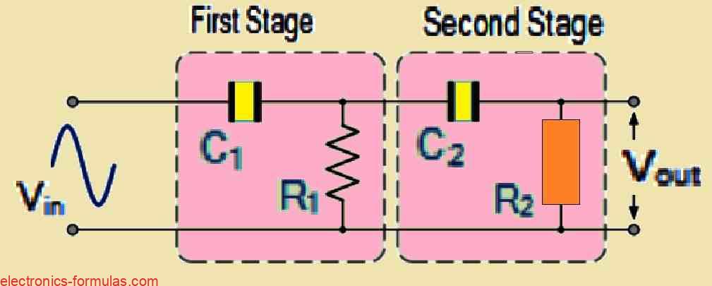
The circuit shown above creates a second-order, two-pole high pass network by connecting or cascading two first-order filters.
Next, much like with the 2nd-order low pass filter, a first-order filter stage may be changed into a second-order form simply by introducing another RC network. The circuit for the second-order high pass filter that results will have a slope of 40 dB/decade (12 dB/octave).
Much like with the low pass filter, here also the resistors and capacitors work together to define the cut-off frequency ƒc, as represented by the following formula:
fc = 1 / 2π√(R1C1R2C2) (Hz)
In reality cascading passive filters to produce higher-order answers gets more difficult to execute effectively.
This problem originates from the impact of each stage’s dynamic impedance (Z) on its surrounding network.
The impedance experienced by the subsequent filter stage (e.g., stage n+1) is directly influenced by the output impedance of the previous stage (stage n). This interaction causes a divergence from the optimal frequency response characteristics for each level.
To decrease the loading effect, a popular method is to use a decade impedance ratio between cascaded stages.
This approach defines the design of the following stage (stage n+1) with a resistor (R(n+1)) ten times greater than the resistor (Rn) in the previous stage (stage n). On the other hand, the capacitor (C(n+1)) in stage n+1 should be one-tenth the value of the capacitor (Cn) in stage n.
This technique, stated mathematically as R(n+1) = 10 * Rn and C(n+1) = Cn / 10, facilitates in maintaining a reasonably consistent voltage across each stage. This reduces the effect of loading on the entire filter response.
According to the above calculation, we could mitigate the loading effect by making the impedance of each subsequent step 10 times the previous stage, thus R2 = 10 * R1 and C2 = 1/10th of C1.
Conclusions
Comparing High and Low Pass Filters:
A passive high pass filter behaves in the opposite manner of a low pass filter. Within the DC zone (0 Hz), the high pass filter generates no output voltage. This activity will continue, until a certain cut-off frequency (fc) is achieved.
The cut-off frequency is the moment, at which the output voltage exceeds 70.7% (or -3 dB, calculated as dB = -20log(Vout/Vin)) of the maximum voltage gain.
Stop and Pass Band Definitions:
The stop band is defined by frequencies that are lower than the cut-off frequency (fc). In contrast, frequencies that surpass fc are within the pass band.
Cut-off Frequency Calculation:
The conventional formula fc = 1/(2πRC), reliably calculates the cut-off frequency (fc) for a high pass filter. In this example R denotes resistance in Ohms (Ω) and C depicts capacitance in Farads. It is worth noting that the resultant output signal has a +45° phase shift at the cutoff frequency (fc).
Lower Distortion in High Pass Filters
In general high pass filters cause less distortion than their low-pass counterparts. High pass filters have a greater working frequency, which gives them an advantage.
Applications for High Pass Filters:
Audio Coupling: One common application for passive high pass filters is in audio amplifiers. They are used as coupling capacitors in between amplifier stages.
Speaker System Signal Routing: High pass filters are used in speaker systems to send high-frequency sounds to the smaller tweeter speakers.
They simultaneously block lower bass signals. These filters may also serve to reduce low-frequency noise and “rumble” distortions.
“Low-Cut” or “Bass Cut” Filters: In the audio domain, high pass filters employed in this technique are commonly referred to as “low-cut” or “bass cut” filters.
Output Voltage Dependence and Differentiator Circuits:
As previously noted, the output voltage (Vout) is determined by the time constant (τ) and the frequency of the input signal.
When a sinusoidal AC signal is introduced to the circuit, it functions as a simple first-order high pass filter. However when the input signal is changed to a square wave with a near-vertical step shift, the circuit’s response changes substantially. In this case the circuit becomes a differentiator.
Previous Assumptions for Input Waveforms:
In our previous filter investigations we figured out that the input waveform was sinusoidal or sine wave. This suggests a basic signal with harmonics functioning in the frequency domain. As a result the filter response is frequently evaluated in the frequency domain.
Introducing the Square Wave Input.
However if we stray from this assumption and feed a square wave signal into the high pass filter, the analysis moves to the time-based domain. A square wave indicates an impulse or step response input.
The impact on the output waveform:
The shift in input signal from sine wave to square wave has a substantial impact on the output waveform. When a square wave is sent into the high pass filter, it generates an output waveform made up of short-duration pulses or spikes, as seen in the picture below…
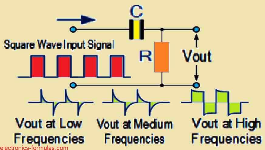
Double-spike response per square wave cycle:
When a square wave is used as the input signal, the RC differentiator circuit creates a unique output response. Each square wave input cycle generates two spikes at the output, which have opposing polarities: one positive and one negative. In particular the magnitude of these output spikes is equal to that of the input signal.
Spike Decay and the Time Constant:
The RC circuit’s time constant (τ) directly affects the rate of decay in these output spikes. The time constant (τ = RC) is determined as the product of resistance (R) and capacitance (C) in the circuit. Moreover the frequency of the input signal influences the spikes’ decay rate.
Dependency on Frequency and Fidelity of Input Signal:
An intriguing finding is that, as the input frequency increases, the output pulses become increasingly similar to the original signal structure. This phenomena could be explained by the RC circuit’s high-pass filtering characteristic. At higher frequencies, the filter provides less resistance to the signal enabling it to flow through with better accuracy.
References: High-pass filter
Leave a Reply