
We all known that a single-stage transistor amplifier, when built as a common-emitter amplifier, may initiate a 180-degree phase shift between its output and input signals. This built-in characteristic of the amplifier design could be used to build an effective RC oscillator circuit.
Interestingly it may be possible for us to construct transistor stages to function as oscillators by strategically adding resistor-capacitor (RC) networks connected around the transistor, which then provides the necessary regenerative feedback without the requirement for a tank circuit.
Thus you will find that such frequency-selective RC connected BJT amplifier circuits are very simple to put together and can be tuned to oscillate at any desired frequency by carefully setting the resistance and capacitance parameters.
To make sure that the above explained RC oscillator is able to sustain its oscillations continuously and non-stop, we must set the circuit to produce sufficient feedback with the correct phase, meaning a sufficient positive (in-phase) Feedback must be provided in the circuit.
Also the voltage gain of the single transistor amplifier could be used to induce a good amount of loop gain into the closed-loop circuit, which ensures that the oscillator is able to generate non-stop oscillations at the selected frequency.
Phase Shift in a RC Oscillator Circuit

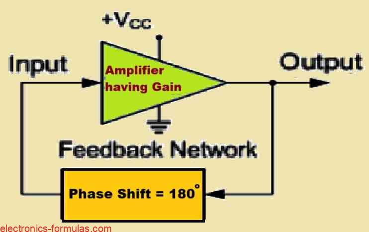
In an RC oscillator circuit we find that the input signal undergoes a phase shift of 180 degrees through the feedback circuit causing the signal to get out-of-phase, which is then subsequently processed through an inverting amplifier stage causing an additional phase shift of 180 degrees.
This concatenation of phase shifts yields a total phase shift of 180o + 180o = 360o degrees, which is equivalent to a phase shift of 0 degrees.
This double phase shifting facilitates the induction of the necessary positive feedback in the circuit. In other words, the aggregated phase shift of the feedback loop of the circuit should be precisely 0 degrees or any multiples of 360 degrees to obtain the identical effects, and this function specifically ensures that a continuous oscillation output of the circuit is sustained.
In an RC Oscillator circuit which basically is built using resistor-capacitor network, we are ale to exploit the characteristic of phase shift between the input signal and the output signal generated by an RC network by carefully combining interconnected RC elements within the feedback branch of the circuit.
This results in a configuration that allows us for an easy adjustment of the phase relationship between the input and output signals.
RC Phase-Shift Configurations

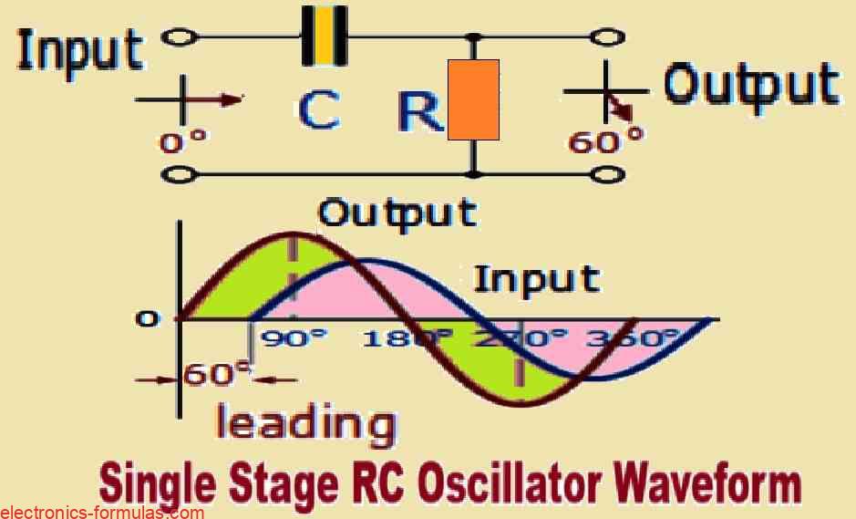
In the circuit shown above we can see a single resistor-capacitor (RC) network. In this type of circuit the output voltage is said to “lead” the input voltage which means that the output voltage reaches its peak before the input voltage does and this leading effect happens at a specific angle which is less than 90 degrees (90°).
In an ideal situation where we have a perfect single-pole RC network, it would be possible for us to achieve a maximum phase shift of exactly 90°.
This 90° phase shift is significant because if we want to create oscillations (which are repetitive variations in a signal), we would require a total phase shift of 180°. Therefore to achieve this requirement within the design of an RC oscillator we need to incorporate at least two single-pole networks.
However in practical applications you may find the above requirement to achieve that precise 90° phase shift for each individual RC stage quire challenging.
So to achieve this we must connect multiple RC stages in a sequence which is known as cascading which helps us reach the necessary phase shift value at the frequency we want for the oscillation, as shown in the following figure.

The actual amount of phase shift which we get in the circuit depends on the specific values of the resistor (denoted as R) and the capacitor (denoted as C) used in the circuit.
This phase shift is also influenced by the frequency at which we want the oscillations to happen. We can determine the phase angle (ɸ) which quantifies this phase shift, through the relationship between R, C, and the selected frequency of oscillation.
Understanding RC Phase Angle Calculations
XC = 1/2πfC, R = R,
Z = √[R2 + (XC)2]
ɸ = tan-1(XC/R)
In the above formulas, XC represents the Capacitive Reactance of the capacitor, R denotes the Resistance of the resistor and the letter f specifies the Frequency.
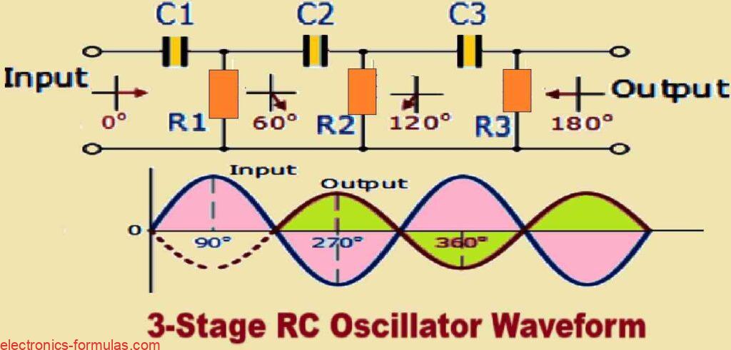
In the straightforward example presented above we have deliberately selected the values of the resistor (R) and the capacitor (C) such that, at the specified frequency of interest, the output voltage leads the input voltage with an angle of approximately 60 degrees.
As a direct consequence of this configuration the phase angle between each successive RC section incrementally increases by an additional 60 degrees.
This cumulative effect results in a total phase difference of 180 degrees between the input and output voltages which can be mathematically represented as three times 60 degrees (3 x 60°).
This phenomenon could be further illustrated in the following vector diagram which effectively depicts the relationships among these phase angles.
Vector Diagram

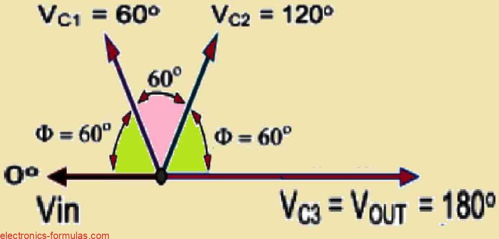
Therefore if we cascade together three such RC networks in a series configuration we are able to generate a cumulative total phase shift of 180 degrees within the circuit at the designated frequency.
This arrangement fundamentally establishes the basis for what is commonly referred to as an “RC Oscillator” which is alternatively known as a Phase Shift Oscillator due to the fact that the phase angle is progressively shifted by a specific amount through each stage of the circuit.
As a result, the phase shift becomes evident as a change in the phase difference between the individual RC stages.
Moreover it is noteworthy that operational amplifier (op-amp) ICs can be easily procured from the local electronics market in quad integrated circuit (IC) packages which allows us to implement multiple stages efficiently.
For instance, we can make use of the well-known options such as the LM124 or the LM324 ICs which enables us to incorporate the four opamp modules for our RC stages if desired.
This easily facilitates the production of the necessary 180 degrees of phase shift at the specified oscillation frequency, further enhancing the functionality and versatility of the oscillator design.
Cascading RC Networks to get 0 degree Phase Shift Output
So now we know that while using an RC amplifier circuit regardless of whether a Bipolar Transistor is used or an Inverting Operational Amplifier is used, it always generates a phase shift of precisely 180 degrees between the input signal and the output signal. This characteristic is a fundamental aspect that may be found in these types of amplifiers.
Now if we consider a circuit in which a three-stage RC phase-shift network is connected as a feedback mechanism between the output and input of the amplifier circuit, we can analyze the cumulative phase shift that this arrangement creates.
In this design we find that the three-stage network generates an individual phase shift of 60 degrees for each of its stages. Therefore when we consider all three stages together, the total phase shift turns into 3 x 60o + 180o = 360o = 0o
Please remember that a phase shift of 360 degrees is effectively equivalent to a phase shift of 0 degrees, simply because these values represent a complete cycle of an AC oscillation waveform.
This relationship is illustrated in the following diagram which clearly shows the mutual actions between these phase shifts in the total feedback mechanism of the amplifier circuit.

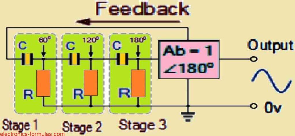
In the above figure, the three RC stages are methodically cascaded together to generate the slope required for producing a constant and non-stop oscillation frequency.
In a system like this, it is critical to recognize that the phase shift inside the feedback loop reaches an important level of -180 degrees. This phase shift happens when each individual RC stage adds a -60 degree phase shift.
To further clarify, we may satisfy this condition by setting jω = 2piƒ = 1/1.732RC. Here the numerical value 1.732 is derived from the fact that (tan 60o = 1.732), which points out the relationship between frequency, resistance, and capacitance in the circuit design.
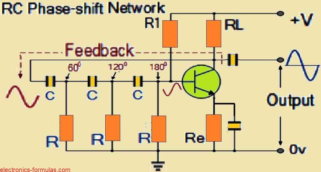
From the above explanation we realize that we have to use several RC phase-shifting networks in an RC oscillator circuit in order to achieve the desired phase shift.
The circuit diagram shown below illustrates the significance of these networks. This methodical construction enables the successive realization of the proper phase characteristics, leading to a more stable and constant oscillation frequency inside the circuit.
Understanding Basic RC Oscillator Circuit

So far we have learned that the RC Oscillator which is also called a Phase-Shift Oscillator, creates a sine waveform output. It does this using regenerative feedback from a resistor-capacitor (RC) ladder network. This feedback works because capacitors have the property to store electric charge, similar to an LC tank circuit.
We can set the RC feedback network to produce either a leading phase shift (phase advance network) or a lagging phase shift (phase retard network). No matter how we do the setup, sine wave oscillations will always occur at a given frequency with an overall phase shift of 360 degrees.
If you want to change the oscillation frequency, then you can adjust the values of the resistors or capacitors in the network. Usually, you will want to keep the resistor values constant and instead use a 3-ganged variable capacitor.
This above aspect is important because capacitor characteristics can get affected by frequency modifications. But, when you adjust the frequency you might also need to change and fine-tune the amplifier’s voltage gain also.
If the three resistors (R1, R2, R3) are equal and the three capacitors (C1, C2, C3) are also equal, then it is possible for us to express the frequency of oscillation from the RC oscillator with the following equation:
fr = 1/2πRC√2N
In the above formula, Where:
- fr represents the output frequency of the oscillator, in Hertz
- R indicates the feedback resistance, in Ohms
- C denotes the feedback capacitance, in Farads
- N represents the number of RC feedback stages.
The parameter in question is the oscillation frequency of the phase shift circuit. In our earlier example we have three stages, which gives us N = 3. And this leads us to calculate N = 3(√2*3 = √6).
If we consider a 4-stage resistor-capacitor (RC) network then N would be 4. Thus we calculate √2 * 4 = √8, and so on for more stages.
The RC combination in the oscillator functions as both a frequency-determining circuit and an attenuator. As the signal moves through each stage, its amplitude keeps decreasing.
One might think that the 3 phase-shift sections work independently, but this is not correct. The total feedback attenuation across all the 3 stages results in an attenuation factor of -1/29 which can be expressed as Vo/Vi = β = -1/29.
Due to this attenuation, the voltage gain of the amplifier must be high enough to compensate the passive losses from the RC network. Therefore to achieve a total loop gain of -1 in our three-stage RC network, the amplifier’s gain needs to be at least 29.
Additionally we must consider the loading effect of the amplifier on the feedback network. This can significantly alter the frequency of oscillations. In some cases the oscillator frequency may increase by upto 25% above the calculated value.
It is advisable for the feedback network to be driven by a high-impedance output and connected to a low-impedance load, just like a common emitter transistor amplifier. Using an operational amplifier is even better, since it meets the necessary conditions for effective operation.
An RC Oscillator using an Op-Amp
Operational amplifier RC oscillators are more commonly used than those based on bipolar transistors or BJTs, when it comes to functioning as RC oscillators. In this type of oscillator circuit, you will find that there is a special operational amplifier configuration that operates with negative gain.
Along with this amplifier we also find a three-stage RC network designed to produce a 180-degree phase shift. This phase shift network has been connected in such a way that it takes the output from the operational amplifier and feeds it back into the same amplifier’s inverting input, as illustrated in the image below.
RC Oscillator Circuit with a Phase-lead using an Op-amp

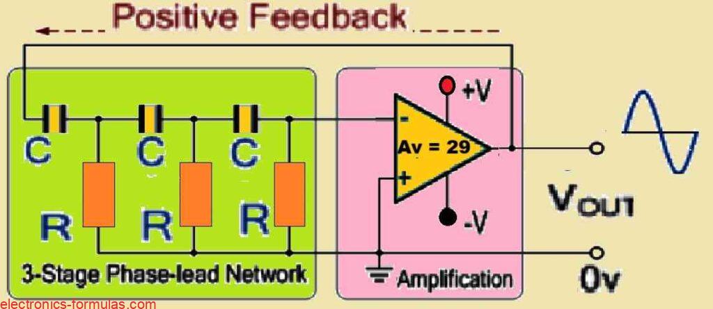
Because the feedback is connected to the inverting input of the operational amplifier, the amplifier is set up in what we call an “inverting amplifier” configuration. This setup naturally creates a 180-degree phase shift.
Meanwhile the RC network also generates an additional 180-degree phase shift at the specific frequency we need.
When we add up these two phase changes (180 degrees from the amplifier and 180 degrees from the RC network), we then obtain a total phase shift of 360 degrees, which equals 0 degrees in a complete cycle.
This kind of feedback circuit is called a phase-lead configuration because the resistors are connected to ground (0V) and the capacitors are connected in series. Put simply, in this configuration the output voltage of the circuit leads the input voltage, resulting in a positive phase angle.
On the other hand we can create a phase-lag configuration by simply rearranging the positions of the RC components. In this case we connect the resistors in series and connect the capacitors to ground (0V), as illustrated in the diagram. With this new setup, the output voltage will lag behind the input voltage, giving rise to a negative phase angle.
RC Oscillator Circuit with a Phase-lag using an Op-amp
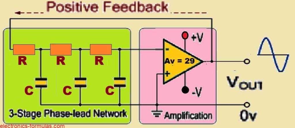
As you can see that the RC components in the feedback network are now oppositely configured compared to our previous phase-lead design, therefore the formula for the frequency of oscillation now changes, as shown below:
fr = √2N/2πRC
Although you can connect just two single-pole RC stages together to achieve the necessary 180 degrees of phase shift (which is 90 degrees plus another 90 degrees), doing so typically results in poor stability for the oscillator, especially at lower frequencies.
One important characteristic of an RC oscillator is its frequency stability, which means that it can maintain a constant frequency sine wave output regardless of whether the load changes or not. If you want to increase the oscillator stability then you can connect three or four RC stages in a cascade configuration.
This design gives us a total of 180 degrees of phase shift (4 phases of 45 degrees each) which considerably improves the stability of the design.
Due to the increasing availability of the quad integrated circuit (IC) packages for operational amplifiers, four-stage RC oscillators are frequently preferred. This design decision makes it easier to construct a four-stage oscillator that provides a 45-degree phase shift across each stages.
Furthermore, RC oscillators have become famous for their stability along with their ability to provide an output frequency with a well defined sine wave. In an RC oscillator circuit, the output frequency will be inversely proportional to the product of resistance (R) and capacitance (C), and this expression can be written as 1/RC.
The above relationship allows for a wider frequency range, especially when considering the addition of a variable capacitor in the circuit.
It must be remembered that RC oscillators have limitations in frequency applications, mostly because of their bandwidth restrictions that may interfere with their ability to generate the intended phase shift at higher frequencies.
Solving an RC Oscillator Problem
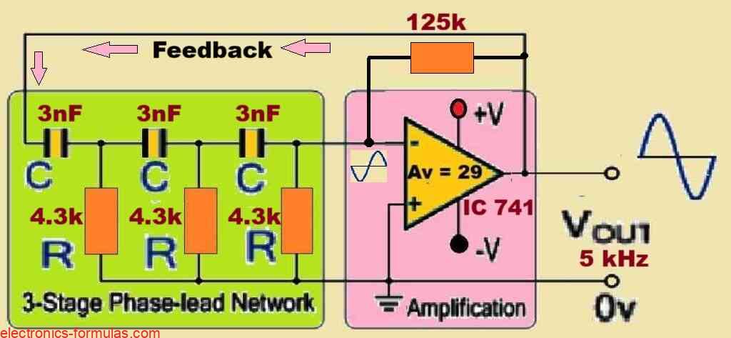
Consider an operational amplifier configured as a 3-stage RC Phase Shift Oscillator. We want this circuit to generate a sinusoidal output frequency of 5 kHz.
We have 3 nF capacitors included in the feedback network. So we want to calculate the value of the resistors which determine the frequency of the circuit, and the value of the feedback resistor required to ensure a sustained oscillations from. We will also draw the resultant circuit diagram at the end of the calculations.
From our previous discussions we know the standard formula for RC phase-shift oscillator is:
fr = 1/2πRC√2N
Since the circuit in question is a 3-stage RC oscillator circuit, so it has to include 3 identical resistors and 3 identical capacitors in the feedback network. The value of the capacitors are 3 nF each and the frequency of oscillation is mentioned as 5 kHz, so using these figures we can calculate the value of the 3 resistors in the following manner:
f = 5 = 1/[2 * π * R * 3√(2 *3)]
R = 1/[2 * π * 5000 * 3 * 10-9√(6)]
∴ R = 4331.64 Ω or 4.33 kΩ
As we learned earlier, the operational amplifiers must have a gain of 29 to ensure a sustained uniform output oscillations. We calculated the value of the feedback resistors to be 4.3 kΩ, therefore in order to ensure the gain of 29 we can accordingly calculate the values of the gain resistor Rf in the following manner:
AV = RF/R = 29
∴ RF = AV * R
∴ RF = 29 * 4.33 = 125.5 kΩ
Now, we can draw the oscillator circuit diagram using an opamp and 3-stage RC feedback using the above calculated component values, as shown below:
In the next upcoming tutorial we will continue our discussion on Oscillators, and talk about another type of RC Oscillator called the Wien Bridge Oscillator, in which we use resistors and capacitors for creating its tank circuit, which provides us with a sine wave output but at a low frequency….until then.
References: RC oscillator