One method for analyzing electrical circuits is the Superposition Theorem. It is applicable to circuits that have several independent sources of voltage or current.
The theorem basically enables us to dissect the functioning of the circuit and examine the role played by each source separately. In order to accomplish this, we temporarily disable all other sources (by the substitution of current sources with open circuits and voltage sources with short circuits).
Next, we calculate the voltage and current resulting from every active source independently. Lastly, we combine the contributions from each unique source algebraically to determine the real voltage or current at each point in the circuit.
To put it another way, superposition allows us to examine the circuit individually for each source and then compile the findings to determine the overall behavior of the voltage and current.
Unlike mesh and nodal analysis, this approach does not need the application of sophisticated mathematical techniques such as determinants and matrix algebra. Because of this, superposition may be used to analyze circuits having both direct current (DC) and alternating current (AC), particularly ones that have several active sources.
The Limitation of the Superposition Theorem:
The fact that superposition is limited to circuits with known component behavior is a drawback. Fortunately, typical passive components such as resistors (R), inductors (L), and capacitors (C) have well-defined voltage-current relationships. The relationships between them are linear, this means that the output would vary proportionately with the input.
Turning Off Sources for Analysis:
Like other techniques for circuit analysis (Kirchhoff’s Laws, Thevenin’s Theorem, Norton’s Theorem, etc. ), superposition necessitates “deactivating” every source in the circuit for a certain amount of time.
In order to do this, we consider current sources as open circuits (no current flow) and voltage sources as short circuits (zero voltage drop). As a result, we are able to determine how each source affects the circuit independently.
Cutting Off Sources:
A short circuit eliminates the voltage source by creating a direct connection between two sites. The voltage drop is zero (v = 0) in a short circuit since there is no voltage differential across it.
Similarly, an open circuit functions as a break in the wire, inhibiting current passage. The current drops to zero (i = 0) since ideal current sources are unable to push current through a discontinuity. We are able to analyze the effects of each source individually by substituting these “deactivated” versions for the original sources.
Dependent sources behave differently.
Dependent sources are distinct from regular sources that produce a constant voltage or current. Their output (voltage or current) is determined by another voltage or current in the circuit or from an external source. Because of this connection, we are unable to just switch them off like regular sources.
Continuing with the T-Circuit:
Consider the T-shaped DC circuit, as discussed in one of our previous posts:
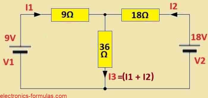
Here, we must determine the current passing through R3, the middle 36Ω resistor, meaning we need to find I3.
As long as we remain consistent throughout the circuit analysis process, it doesn’t matter whether we analyze the circuit in a clockwise or counterclockwise manner. To get things started, we will replace the 18-volt battery with a short-circuit, allowing the 9-volt battery to function alone on the circuit, as illustrated below.

It is evident that when voltage source V2 is shorted to ground, the 18Ω resistance on the right becomes practically parallel to the 36Ω resistance in the middle. The corresponding parallel resistance of the two parallel-connected resistors is subsequently calculated as follows:
REQ1 = (R2 * R3) / (R2 + R3) = 18 * 36 / 18 + 36 = 12 Ω
The equivalent parallel resistance REQ1, which is 12 Ω, is connected in series with the left side 9 Ω resistance R1, creating a total series circuit resistance of (9 + 12) = 21 Ω for the current I1.
Because node A has a 9V battery supply, we may calculate the voltage there by using the voltage divider rule.
VA = V1[REQ1 / (R1 + REQ1)] = 9(12 / 9 + 12) = 5.14 Volts
How to Calculate the Current, IR3(1)
The 9 volt battery supply, V1, drives the 36 Ω resistance, R3. Therefore, the current passing via R3 can be calculated as follows:
IR3(1) = VA/R3 = 5.14/36 = 0.142 Amp or 142 ma
This means that when V1 acts alone in the circuit and the battery voltage is 9 V, the current that passes via resistance R3 is 142 ma.
As there exist two parallel branches of resistance, 36 Ω and 18 Ω, comprising the voltage VA of 5.14 volts at node A, we are able to independently confirm this value again in case we would like to:
I1 = 9/21 = 0.42 A, and IR2 = 5.14/18 = 0.28 A
How to Calculate the Current, IR3(2)
With the identical approach and deduction as done above, you can calculate the current passing via the resistor, R3, which is powered by the 18-volt battery, V2.

In order for the 18 volt battery V2 to operate alone in the circuit, the 9 volt battery V1 is swapped out with a short. Once more, resistances R1 and R3 have two parallel branches, and the equivalent parallel resistance of these resistances can be calculated as follows:
REQ2 = (R1 * R3) / (R1 + R3) = 7.2 Ω
The equivalent parallel resistance REQ2 of 7.2 Ωs is now connected in series with the right-hand 18Ω resistance R2, providing a total series resistance of (18 + 7.2) = 25.2 Ωs for the current I2 to pass through.
Yet again, because of V2, we can calculate the voltage at node A by applying the voltage divider rule.
VA = V2[(REQ2 / (R2 + REQ2)] = 18(7.2 / (18 + 7.2)] = 5.14 Volts
This voltage at node A, 5.14 volts, coincidentally has an identical value for both of the voltage sources that are acting in either direction. Next, using the 18 volt battery source V2, the current passing via the 36 Ω resistance R3 can be calculated once more, and it comes out to be:
IR3(2) = VA/R3 = 5.14/36 = 0.142 A, or 142 mA
presently, all we need to do is to determine the algebraic total of the two calculated currents, IR3(1) and IR3(2), to get the finalized value and direction of IR3. This is provided as:
The Direction and Value of IR3.
IR3 = IR3(1) + IR3(2) = 0.142 + 0.142 = 0.284 Amps, or 284 mA
This, as we discovered in the earlier circuit analysis lessons, is exactly the same value of 0.284 Amperes, thanks to Kirchhoff’s circuit rules, Thevenin, and Norton’s Theorems.
The voltage at node A and, consequently, the voltage drop across R3 may be determined using Ohm’s Law as soon as both power supplies have been restored to the circuit. Ohm’s law states that VR3 = IR3 x R3 = 0.284 * 36 = 10.22 volts. This is the exact identical value as originally identified in the earlier courses on circuit analysis.
As we’ve shown, the superposition theorem may be applied to reduce the mathematical complexity of analyzing any linear network with two or more sources of voltage or current. Furthermore, any network with both dc and ac sources might use this theorem.
But take note that because electric power is a non-linear variable that has a value inversely proportional to the square of the voltage (V2/R) and directly proportional to the square of the current (I2*R), the superposition theorem is not applicable to this.
Solving another Superposition Theorem Problem
Now we’ll add a source of current to the circuit and apply the superposition theory to get the voltage drop over the 2Ω resistor, R1.
Circuit Diagram of Superposition

Once more, we must analyze the circuit by shorting off voltage sources and opening circuit current sources to ensure that there is only ever one voltage source powering the circuit. The 8 A current source is subsequently opened, and the circuit can be studied by supplying the 18 V voltage source as indicated.

The circuit now definitely looks like a series resistor circuit linked across V1, as can be seen. Kirchhoff’s Voltage Law (KVL) states that V1 is equal to I1(R1 + R2 + R3). The current, I1, passing through this series circuit may be found using Ohm’s law.
I1 = V1 / (R1 + R2 + R3) = 18 / (2 + 3 + 5) = 1.8 Amps
Consequently, assuming the series circuit is receiving 1.8 amps of current. Calculating the specific voltage drop across resistor R1 yields the following result:
VR1(1) = I1 x R1 = 1.8 x 2 = 3.6 volts
Thus, the 18 volt battery supply causes a 3.6 volt voltage drop over resistor R1. In case we wanted to, we could additionally calculate the rest of the voltage drops throughout the remaining part of the loop by applying the voltage divider rule.
If the 8 amp current source is restored into the circuit and V1, the voltage source is now shorted out. The circuit as a result looks like this:

Given that we have parallel linked resistances across the 8 amp current source, we observe that the circuit we have created is what is known as a current divider. Two parallel branches are subjected to the current source. One branch has resistors R1 and R2 connected in series, whereas the other branch has resistor R3 alone.
The total current in the circuit is equivalent to the combined value of all the parallel branch currents, according to Kirchhoff’s Current Law (KCL). What this means is, IT = 8A = I1 + I2, and we must determine the current that passes through this parallel branch as we are curious regarding its voltage drop across resistor R1.
According to the current divider rule, the total current multiplied by the ratio of total current equals the current flowing via one branch. Next, we calculate the current flowing along parallel branches R1 and R2 as follows:
I1 = [(R1 * R2) / (R1 + R2 + R3)] * IT = [(2 * 3) / (2 + 3 + 5)] * 8 = 4.8 Amps
Because resistors R1 and R2‘s left parallel branch is receiving 4.8 amps of current, we could apply Ohm’s law to get the voltage drop across R1.
VR1(2) = I1 x R1 = 4.8 x 2 = 9.6 volts
Keep in mind that the current is going to be distributed uniformly across the parallel branches when the resistive values of each branch are exactly the identical, as demonstrated in this example. The branch with the highest resistive value will have a smaller current passing across it if the resistive values vary, and vice versa.
As a result, after reconnecting the 18 V voltage source and the 8 A current source to the circuit, the actual voltage measured across resistor R1 is as follows:
VR1 = VR1(1) + VR1(2) = 4V + 9.6V = 13.6 Volts
As before, the voltage drops between resistors R2 and R3 could be found using the same methods of analysis.
Summary
Imagine a circuit, with multiple power sources, like batteries.
The Superposition Theorem helps us analyze the voltage and current at any point in this circuit.
It basically says, we can break down the effects of each power source one at a time.
Heres the trick:
Pretend each power source works alone.
Ignore (short- circuit for voltage, open-circuit for current) all the other power sources for now.
Analyze the circuit with this single active source to find the voltage or current you’ are interested in.
Do this for each power source, one by one.
Finally add up all these individual effects to get the total voltage or current at that point when all the power sources are working together.
Important Points:
This only works for circuit s that behave consistently regardless of the size of the input (linear circuits).
It might be time-consuming for circuits with many power sources. There might be better methods like nodal analysis or mesh analysis in those cases.
Be mindful of positive-negative signs and flow directions when combining the effects of all the supply sources.
References: Superposition theorem
What is the Superposition Theorem
Leave a Reply