
A digital logic AND gate is a type of circuit that produces an output based on its two inputs. For an AND gate you will find that its output is only “HIGH” (which means true or 1) whenever both of its inputs are “HIGH” (true or 1). If we turn either of inputs “LOW” (false or 0), the output will also turn “LOW” (false or 0).
Let me explain this in a different way, the AND gate’s output will be “LOW” if at least one of its inputs is “LOW.” In other words, we may see that the gate only produces a “HIGH” output if both of its inputs are “HIGH.”
We can show the logical operation of an AND gate by using the multiplication symbol (.) in Boolean algebra. For two inputs, A and B, we can write the Boolean expression in the following manner:
A⋅B = Q, where Q is the output.
In simpler terms:
If we make both the inputs A and B as true (or HIGH), then the output Q also becomes true (or HIGH).
If we make either of the inputs A or B (or both) as false (or LOW), then the output Q becomes false (or LOW).
Understanding 2-input Transistor AND Gate
We can build a simple 2-input AND gate by configuring RTL Resistor-transistor switches as depicted in the following figure, in which the inputs are connected directly with the bases of the transistors. In order to get an output Q both the transistors will need to be turned “ON” and saturated.
Logic AND gates are implemented in digital circuits to perform specific logical functions. These are represented using a symbol whose shape visually illustrates the AND operation.
Symbol

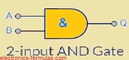
Truth Table
| B | A | Q |
| 0 | 0 | 0 |
| 0 | 1 | 0 |
| 1 | 0 | 0 |
| 1 | 1 | 1 |
Boolean Expression Q = A.B, we say this as A AND B gives Q
Understanding 3-input Logic AND Gate
Symbol

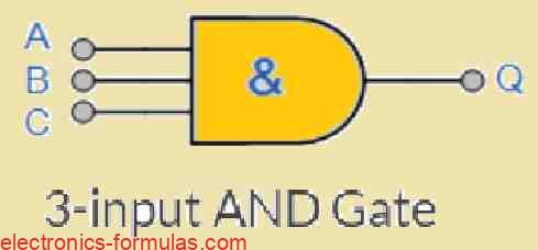
Truth Table
| C | B | A | Q |
| 0 | 0 | 0 | 0 |
| 0 | 0 | 1 | 0 |
| 0 | 1 | 0 | 0 |
| 0 | 1 | 1 | 0 |
| 1 | 0 | 0 | 0 |
| 1 | 0 | 1 | 0 |
| 1 | 1 | 0 | 0 |
| 1 | 1 | 1 | 1 |
Boolean Expression Q = A.B.C, we say this as A AND B AND C gives Q
The Boolean expression for the AND function makes use of a dot (.) to represent a binary operation, meaning it combines two inputs at a time. By doing this it allows AND gates to be hooked up in series, or “cascaded,” to work with more than two inputs.
However in reality we find that commercially available AND gate integrated circuits (ICs) mostly manufactured with either 2, 3, or 4 inputs. If you need an AND gate with more inputs, you would need to string several of these standard ICs together to get the desired number of inputs.
Understanding AND Gate Multiple-input

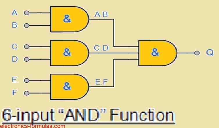
Therefore, for the above shown 6-input AND gate, the Boolean Expression will be as given below:
Q = (A.B).(C.D).(E.F)
Alternatively we can also express the above as:
A AND B AND C AND D AND E AND F gives an output Q
If suppose you intend to work with an odd number of inputs, you can simply turn any of the “unused” inputs HIGH, by connecting them directly to the power supply positive through an appropriate “Pull-up” resistors.
The following table provides us with the most prevalent range of digital logic AND gate IC’s available in the market:
| Logic Type | Part Number | Configuration |
|---|---|---|
| TTL | 74LS08 | Quad 2-input |
| TTL | 74LS11 | Triple 3-input |
| TTL | 74LS21 | Dual 4-input |
| CMOS | CD4081 | Quad 2-input |
| CMOS | CD4073 | Triple 3-input |
| CMOS | CD4082 | Dual 4-input |
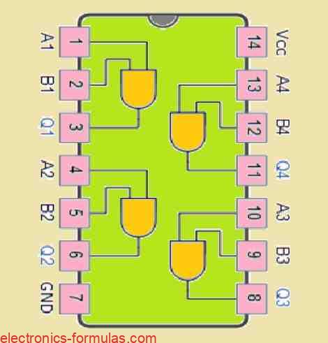
7408 Quad 2-input AND Gate

In the next tutorial which discusses Digital Logic Gates, I will explain you regarding how the digital logic OR Gate functions, and how these ICs can be implemented in TTL and CMOS logic circuits, along with its Boolean Algebra definition and truth tables.
References: AND gate