In order for a signal amplifier to do its job properly and make sure that the output signal does not get distorted in any way it is really important to have some kind of DC Bias applied to its Base or Gate terminal.
You see, a DC bias is necessary because it allows the amplifier to effectively boost the input signal throughout its entire cycle.
This is done by setting the bias “Q-point” as close to the center of the load line as we can possibly get.
When we set the bias Q-point in this way, we end up with what is known as a “Class-A” type amplification configuration.
The most typical setup for this kind of amplification is the “Common Emitter” configuration when we are dealing with Bipolar transistors or if we are using unipolar FET transistors, we would go with the “Common Source” arrangement.
Now let us talk about how we measure the Power, Voltage, or Current Gain—basically how much amplification the amplifier provides.
This is determined by taking the peak output value and dividing it by the peak input value (Output ÷ Input).
However if we happen to make a mistake while designing our amplifier circuit and end up placing the biasing Q-point in an incorrect spot on the load line, or if we apply an input signal that is too large for the amplifier to handle, then what happens is that the output signal might not accurately reflect the original input signal waveform.
In simpler terms this means that the amplifier will experience something that people often refer to as Amplifier Distortion. So take a look at the common emitter amplifier circuit illustrated below:
Understanding Common Emitter Amplifier Circuit
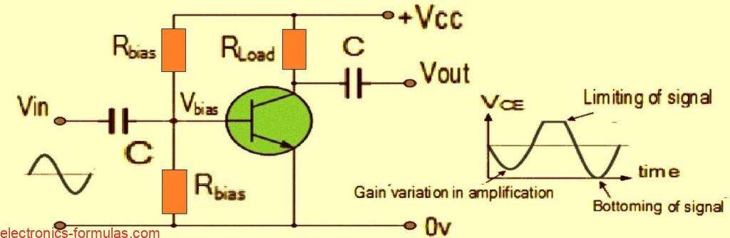
Now let’s investigate why the output signal waveform might get all distorted and messy. There are a few reasons for this happening:
First off all, amplification might not be happening evenly throughout the entire signal cycle, and that could be due to some incorrect biasing levels messing things up.
Then there is the chance that the input signal is just way too big which can push the amplifier’s transistors to their limits because they are constrained by the supply voltage.
Also we have to consider that the amplification is not always a linear signal across all the different frequencies of inputs we throw at it.
When all these factors come into play, it basically means that during the whole amplification process of our signal waveform, we have ended up with some kind of Amplifier Distortion.
Now amplifiers are designed with a pretty straightforward goal, they take those tiny little voltage input signals and pump them up into much larger output signals.
This means that the output signal is always fluctuating based on a certain factor or value known as gain which gets multiplied by the input signal across all input frequencies.
Remember when we talked about this multiplication factor? That is what we call the Beta (β) value of the transistor.
When we look at common emitter or common source type transistor circuits, they do just fine with small AC input signals.
However there is this one big drawback, the calculated spot for the bias Q-point of a bipolar amplifier relies on the same Beta value for all transistors involved.
The catch here is that this Beta value can actually differ from one transistor to another even if they are of the same type.
In simpler terms just because two transistors are supposed to be identical does not mean their Q-points will match up perfectly due to those little quirks in manufacturing tolerances.
As a result of all this variability, amplifier distortion can rear its ugly head because the amplifier is not behaving linearly.
This leads us to a specific kind of amplifier distortion known as Amplitude Distortion.
But do not worry too much. If you choose your transistors and biasing components carefully, you can definitely help reduce the impact of amplifier distortion and keep things running smoothly.
Amplitude distortion can induce distortion in amplifiers
A shift in the Q-point causes amplitude distortion, which can happen when the frequency waveform’s peak values are attenuated. Amplification might not take place during every phase of signal cycle. Below, you can see the output waveform’s non-linearity.
Analyzing Amplitude Distortion due to Wrong Biasing
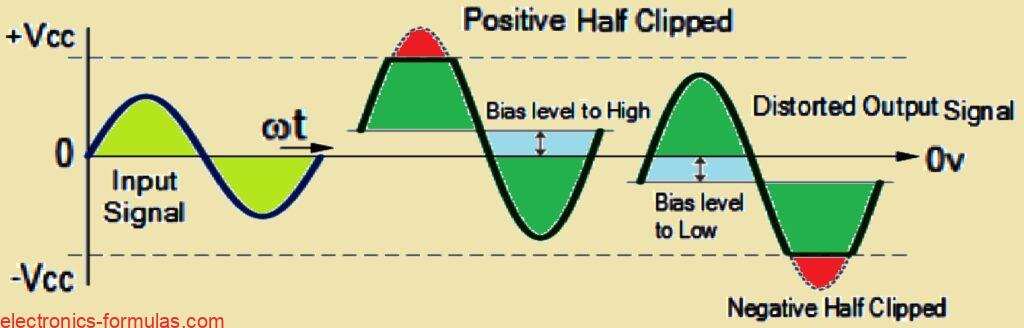
If the biasing point of the transistors is just right then the output waveform should look pretty much like the input waveform, just larger because it’s been amplified.
However if there isn’t enough bias and the Q-point ends up sitting in the lower half of the load line, then what you’ll see is an output waveform that resembles the one on the right. In this case, the negative half of the output waveform gets “cut-off” or clipped.
On the flip side, if there’s too much bias and the Q-point is pushed into the upper half of the load line then you will see an output waveform similar to the one on the left where the positive half gets “cut-off” or clipped.
Now when you set the bias voltage too low during the negative half of the cycle, the transistor doesn’t fully conduct.
This means that during that time, the output is basically determined by the supply voltage.
Conversely when you set the bias too high, what happens is that during the positive half of the cycle the transistor saturates. This saturation causes the output to drop nearly down to zero.
Even if you manage to get that biasing voltage level just right, theres still a chance for distortion in your output waveform.
This can happen if a really large input signal gets amplified by the circuit’s gain.
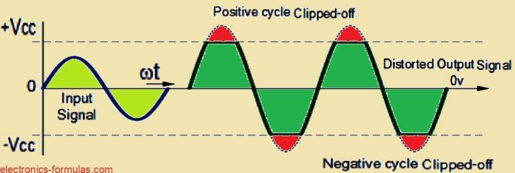
When this occurs you’ll notice that both the positive and negative sections of your output voltage signal get clipped and no longer look like a nice sine wave, even though your biasing is correct.
This kind of distortion in amplitude is known as Clipping, and it happens because you’re “over-driving” the input of your amplifier.
When your input amplitude goes beyond a certain point and becomes too large, this clipping effect becomes quite significant.
It forces your output waveform signal to exceed what your power supply can handle. As a result both the peak (the positive half) and trough (the negative half) parts of your waveform end up getting flattened out or “clipped-off.”
To prevent this from happening, it is important to limit the maximum value of your input signal to a level that will stop this clipping effect from occurring.
Amplitude Distortion Caused by Clipping
So let us talk about Amplitude Distortion for a moment. This kind of distortion really puts a damper on how efficiently an amplifier circuit operates.
You see those “flat tops” that show up in the distorted output waveform often caused by things like improper biasing or pushing the input too hard do not actually do anything to boost the strength of the output signal at the frequency we really want.
Now on a different note it is pretty interesting to point out that some famous guitarists and rock bands actually dig that gritty distorted sound.
They intentionally go for that highly distorted or “overdriven” effect by clipping the output waveform heavily right up to both the positive and negative power supply rails.
If you crank up the amount of clipping on a sinusoidal waveform you will end up generating so much amplifier distortion that the output starts to look a lot like a “square wave.”
This square wave shape can then be super useful in electronic or digital synthesizer circuits.
Additionally we have noticed that when dealing with a DC signal the gain level of the amplifier can change depending on the signal amplitude.
But it is not just Amplitude Distortion we need to be aware of; there are other types of distortion that can pop up in amplifier circuits when working with AC signals.
These include Frequency Distortion and Phase Distortion which can also affect how our amplifier performs.
Amplifier Distortion Caused by Frequency Distortion
So let us talk about Frequency Distortion which is yet another kind of distortion you might encounter in amplifiers specifically in transistor amplifiers.
This type of distortion happens when the amount of amplification changes depending on the frequency of the input signal.
Now in the real world most of the signals that a practical amplifier is designed to boost consist not just of the main signal waveform what we call the “Fundamental Frequency” but also include a bunch of other frequencies that we refer to as “Harmonics” layered on top of it.
Typically these harmonics are much smaller in amplitude compared to the fundamental frequency so they usually do not mess with the output waveform too much if at all.
However things can get a bit tricky if those harmonic frequencies start to increase in amplitude relative to the fundamental frequency.
In such cases you might notice that the output waveform becomes distorted.
To illustrate this point further let us take a look at the waveform shown below.
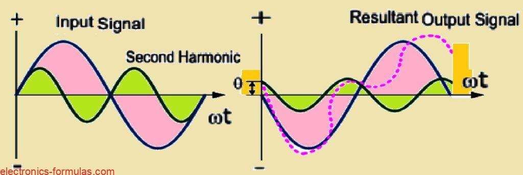
How Harmonics leads to Frequency Distortion
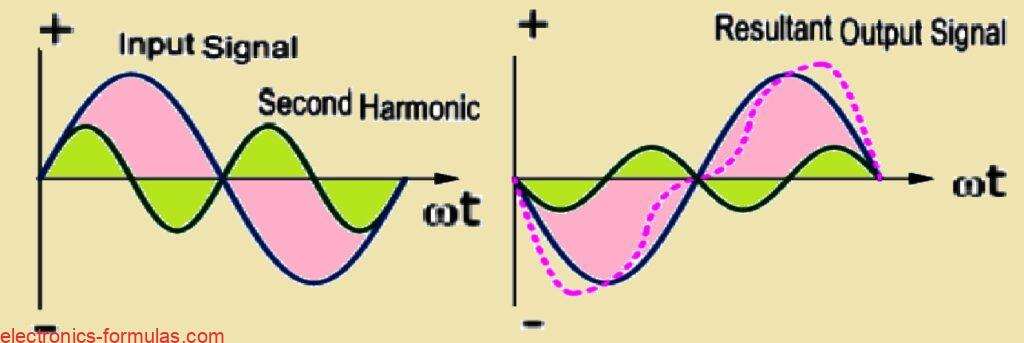
In the example we have just discussed the input waveform is made up of the fundamental frequency along with a second harmonic signal.
If you take a look at the output waveform displayed on the right side you will notice how it looks.
Now frequency distortion comes into play when the fundamental frequency interacts with that second harmonic leading to some distortion in the output signal.
To break it down harmonics are essentially multiples of that fundamental frequency we started with and in this straightforward example we specifically utilized a second harmonic.
So when we talk about the frequency of that harmonic it turns out to be twice the value of the fundamental frequency expressed mathematically as 2*ƒ or simply 2ƒ.
If we were to extend this idea further we could think about a third harmonic which would be represented as 3ƒ then there is a fourth harmonic at 4ƒ and this pattern continues indefinitely.
It is important to note that frequency distortion caused by these harmonics is always something to consider in amplifier circuits that include reactive elements like capacitance or inductance.
Amplifier Distortion Due to Phase Distortion
Now let us shift gears a bit and talk about another kind of distortion known as Phase Distortion or Delay Distortion.
This particular type of distortion happens in a non-linear transistor amplifier when there is a noticeable time delay between when the input signal is applied and when it actually shows up at the output.
If we assume that at the fundamental frequency there is no phase change between the input and output signals meaning they are perfectly aligned the resulting phase angle delay will actually be determined by the difference between the harmonics and that fundamental frequency.
This time delay is not just random; it depends on how the amplifier is constructed and tends to increase progressively with frequency across the amplifier’s bandwidth.
To illustrate this concept more clearly let us take a look at the waveform below.
How Delay leads to Phase Distortion
When we look beyond just the high-end audio amplifiers we find that most practical amplifiers tend to exhibit some level of Amplifier Distortion.
This distortion usually comes from a mix of “Frequency Distortion” and “Phase Distortion” along with amplitude distortion as well.
In many common instances such as with audio amplifiers or power amplifiers, distortion created by these amplifiers is typically not a problem unless it is really excessive or severe.
In such instances it will usually have no substantial effect on how the amplifier works or the quality of the music it produces.
References:
Distortion in Transistor Amplifier
Leave a Reply