An inductive coil generates a self-induced electromotive force (emf) opposing the initial emf in response to an AC supply. This phenomenon, termed inductive reactance, imposes limitations on the flow of time-varying current in the circuit.
Inductors and Energy Storage
Inductors, also known as chokes, are coils wound around air or ferromagnetic material to enhance their inductance. They store energy in a magnetic field when voltage is applied across their terminals.
Current Rise and Steady State in Inductors
The rise of current in an inductor is governed by its self-induced emf, which is proportional to the rate of change of current. Current stabilizes at a steady state approximately after five time constants, as the self-induced emf decays to zero, causing the inductor to behave like a short circuit.
AC Inductor Behavior and Reactance
In alternating current circuits, inductor behavior deviates from steady-state DC circuits. The opposition to current flow in AC circuits relies on inductance and the frequency of the applied voltage waveform.
AC Resistance and Inductive Reactance Calculation
The AC resistance of a coil, expressed as complex numbers, determines the actual resistance to current flow. Known as reactance (denoted as "X"), it is distinct from DC resistance ("R"). The inductive reactance (XL) of an inductor, measured in Ohms, can be calculated using the provided formula.
XL = 2πƒL
In the given context:
- XL represents the inductive reactance measured in Ohms (Ω).
- π (pi) is a constant with a numerical value of 3.142.
- ƒ denotes the frequency in Hertz (Hz).
- L stands for inductance measured in Henries (H).
Inductive reactance can be alternatively expressed in radians by using Omega (ω), where ω is equal to 2π times the frequency (ƒ).
XL = ωL
When a sinusoidal voltage is applied to an inductive coil, the back electromotive force (emf) counters the current fluctuations. In an ideal inductive coil with zero resistance, the impedance, a complex number, is equivalent to its inductive reactance. Reactance is depicted as a vector, considering both magnitude and direction, in the illustrated circuit.
Inductive Reactance in the Presence of Sinusoidal AC Voltage
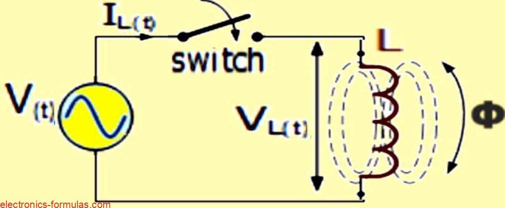
Pure Inductive Circuit: Basic Setup
In a pure inductive circuit, the fundamental configuration comprises a pure inductance (L) measured in Henries (H) connected to a sinusoidal voltage, V(t) = Vmax sin ωt. When the switch is closed, the current starts rising, generating a magnetic field in the coil that opposes the change in current.
DC Circuit and Current Reversal
In a DC circuit, just before reaching its maximum, the voltage polarity changes, causing the current to reverse direction. This reversal is delayed by the self-induced back electromotive force (emf) in the coil, resulting in a 90o delay in a pure inductive circuit.
Perfectly Inductive Circuit: Voltage Leading Current
In a perfectly inductive circuit, the applied voltage reaches its peak a quarter of a cycle (1/4ƒ) earlier than the current. This implies that the voltage "LEADS" the current by 90o.
AC Inductance Illustrated through Sinusoidal Waveforms
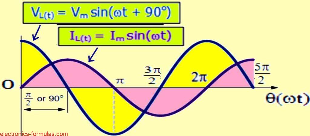
In a purely inductive circuit, the phasor diagram shows that when you use voltage as a reference, the current lags behind the voltage by 90 degrees or one quarter of a cycle, as demonstrated in the vector diagram below.
Phasor Diagram for AC Inductance
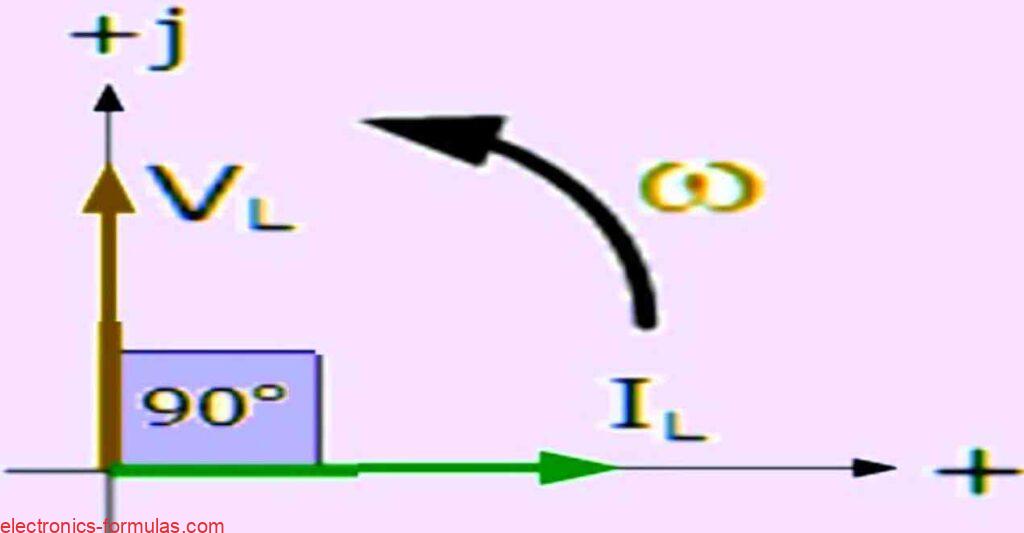
Phase Relationship in Pure Inductor Circuit
In a pure inductor, voltage (VL) "leads" current (IL) by 90o or IL "lags" VL by 90o.
Memory Aid: ELI
Use the mnemonic "ELI" to remember the phase relationship: Electromotive force (E) first, followed by Inductance (L), and then Current (I). This holds true for any phase angle in a pure inductor circuit.
Effect of Frequency on Inductive Reactance
- At 50Hz, the current is delayed by 90o, reaching its peak value in "T secs."
- With a 100Hz supply, the current still lags by 90o, but its peak value is lower due to the reduced time to reach maximum, and increased flux change rate.
- Increasing frequency or inductance raises the overall inductive reactance. As frequency approaches infinity, the reactance and impedance increase to act like an open circuit. Conversely, at low frequencies or DC, the reactance approaches zero, acting like a short circuit. Inductive reactance is directly proportional to frequency, with low values at low frequencies and high values at higher frequencies.
Relationship Between Inductive Reactance and Frequency
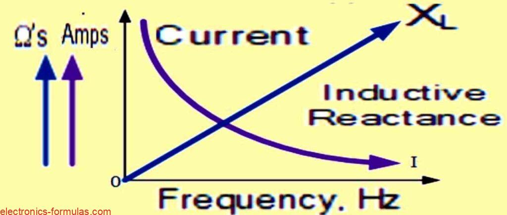
The inductive reactance (XL) of an inductor is directly proportional to the frequency (ƒ) across it. This relationship is expressed as XL α ƒ. This occurs because the back electromotive force (emf) generated in the inductor is determined by multiplying its inductance by the rate of change of current within the inductor.
Impact of Frequency on Current
As the frequency increases, the value of current flowing through the inductor decreases.
Reactance of Pure AC Inductance at Different Frequencies
The effect of very low and very high frequencies on the reactance of a pure AC inductance can be illustrated using following images:

The next formula can be used in an AC circuit with pure inductance:
Current (I) = Voltage / Opposition to Current Flow = V / XL
Equation Origins
The equation's foundation lies in understanding self-induced electromotive force (emf) within an inductor, governed by Faraday's Law and the concept of "self-induction."
Self-Induction Dynamics
In an inductive coil, electric current prompts "self-induction." This results from the rate of change in alternating current inducing an emf within the same coil, opposing the current change.
Self-Inductance and Voltage
"Self-inductance" denotes the coil's resistance to current changes due to its magnetic field. The following equation for the maximum voltage of self-induced emf corresponds to the peak rate of current change:
VL(T) = LdiL(t)/dt = Volts (V)
VL(T) = (d/dt)L iL(t) Volts
In this context, (d/dt} ) symbolizes the rate of current change over time. The expression for the sinusoidal current coursing through the inductive coil (L) and generating magnetic flux is as follows:
iL(t) = Imax sin(ωt)
We can also express the above as:
VL(T) = (d/dt)L x Imax sin(ωt)
Upon differentiation with respect to the sinusoidal current, we obtain:
VL(T) = (d/dt)LImax sin(ωt) = ωLImax cos(ωt + θ)
The trigonometric equivalence, cos(ωt + 0°) = sin(ωt + 0° + 90°), reveals that a cosine waveform is essentially a sine waveform shifted by +90°. Subsequently, we can express the earlier equation in sine wave form to characterize the voltage across an AC inductance as follows:
VL = Vmax sin(ωt + 90o)
In this context, VMAX = ωLIMAX = √2VRMS represents the maximum voltage amplitude. The phase difference, denoted by θ = + 90o, signifies the angle between the voltage and current waveforms. Specifically, in a pure inductor, the current lags the voltage by 90°.
In the realm of phasors, the voltage across the coil is expressed as:
VL = jωL1
In the above formula, jωL denotes jXL = 2πƒL = Z (impedance)
Expressed in Polar Form, this would be represented as XL∠90o, where:
XL∠θ = VL∠+90o / IL∠0o

XL∠θ = jωL = 0 + jXL = ωL∠90o = Z∠90o
Analyzing AC through a Series R + L Circuit
In a theoretical scenario, we observed that the current in a purely inductive coil lags the voltage by 90 degrees. However, real-world electrical components, such as coils, relays, solenoids, and transformers, inevitably have some resistance due to the inherent resistivity of copper wire.
Impure Inductance: R in Series with L
To represent this reality, we can envision an inductive coil with internal resistance, denoted as "impure inductance." The circuit configuration includes a resistance (R) in series with an inductance (L), creating a combined impedance.
Voltage in AC Circuit with Inductance and Resistance
In an AC circuit featuring both inductance (L) and resistance (R), the voltage (V) across the combination becomes the phasor sum of the component voltages, VR (voltage across resistance) and VL (voltage across inductance).
Phase Difference and Φ
The resulting current still lags the voltage, but by an angle less than 90 degrees, determined by the phasor sum of VR and VL. The new phase angle, denoted by the Greek symbol phi (Φ), represents the phase difference between the voltage and current waveforms.
Practical Circuit Example
Illustrating this concept, imagine a circuit as shown below, where a non-inductive resistance (R) is connected in series with a pure inductance (L). This configuration allows us to observe and analyze the interplay of resistance and inductance in an AC circuit.
Circuit with Resistance in Series with Inductance
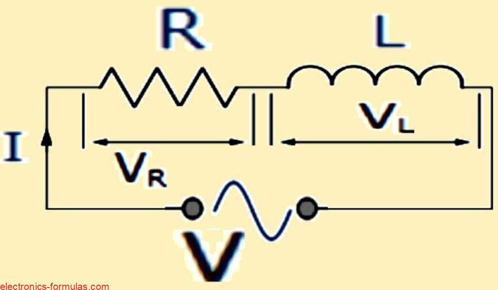
In this RL series circuit, current is shared between resistance and inductance, while voltage is made up of VR and VL. The combined voltage can be found through calculations or a vector diagram. The current is used as the reference point in a series AC circuit for constructing the diagram. Individual vector diagrams for resistance and inductance are shown below:
Vector Diagrams Depicting the Two Pure Components
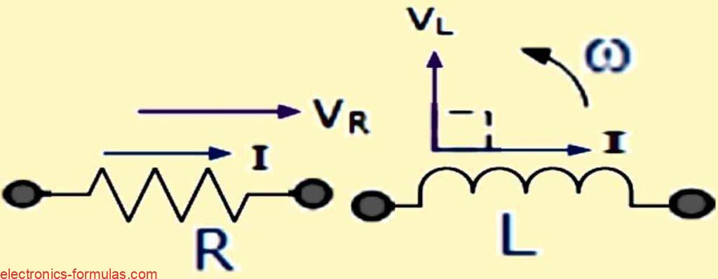
The text above and our previous lesson on AC Resistance show that voltage and current are in phase in a resistive circuit. Therefore, we can draw vector VR on top of the current vector with the same scale.
The text also shows that in a pure AC inductive circuit, the current lags behind the voltage. This means vector VL is 90 degrees ahead of the current vector, keeping the same scale as VR, as shown below.
Diagram illustrating the resultant voltage in vector form

If we look at the vector diagram above, we can notice that OB is the line that represents the current in the horizontal direction and OA is the line that shows the voltage across the resistor that has the same phase as the current. OC is the line that indicates the voltage across the inductor that is 90o ahead of the current, so we can still say that the current lags the inductive voltage by 90o. OD is the line that gives us the total voltage from the source. So:
V is the root mean square (rms) of the voltage applied to the circuit.
I is the rms of the current flowing through the circuit in series.
VR is the voltage drop across the resistor, which has the same phase as the current.
VL is the voltage drop across the inductor, which is 90 degrees ahead of the current.
In a pure inductance, the current is exactly 90o behind the voltage. This means that the individual voltage drops VR and VL form a right-angled voltage triangle OAD, as shown above. We can use Pythagoras theorem to calculate the resultant voltage across the resistor/inductor ( RL ) circuit mathematically.
Since the voltage across the resistor (VR) is equal to the product of the current (I) and the resistance (R), and the voltage across the inductor (VL) is equal to the product of the current (I) and the inductive reactance (XL), the total voltage applied to the circuit (V) will be the vector sum of VR and VL, as shown below:
- V2 = V2R + V2L
- V = √(V2R + V2L)
- V = √(I.R)2+ (I.XL)2)
- ∴ I = V / √(R2 + X2L)
The impedance, Z of the circuit is given by the expression √(R2 + X2L), where R is the resistance and XL is the reactance.
Understanding Impedance in AC Circuits
In AC circuits, Impedance (Z) serves as the total opposition to current flow, incorporating both Resistance (the real part) and Reactance (the imaginary part). It is measured in Ohms (Ω) and varies with the circuit's frequency (ω), affecting its reactive components. In series circuits, impedance is the sum of resistive and reactive components.
Complex Representation of Impedance
Impedance can be expressed as a complex number, Z = R + jXL, where R is resistance and XL is reactance. However, it's crucial to note that impedance isn't a phasor but the outcome of combining two or more phasors.
Triangular Representation
Dividing the sides of the voltage triangle by current (I) yields another triangle representing the circuit's resistance, reactance, and impedance, as indicated in the following diagram:
- Impedance, Z = V / I
- Z = √(R2 + X2L)
- Z2 = R2 + X2L
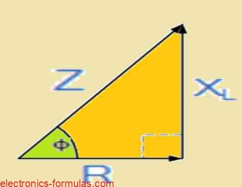
Consequently we have: ( Impedance )2 = ( Resistance )2 + ( j Reactance )2 where j indicates the 90o phase shift.
From this we realize that the positive phase angle, voltage and current angle θ is expressed as:
- Z2 = R2 + X2L
- cosΦ = R/Z
- sinΦ = XL/Z
- tanΦ = XL/R
Simplifying Circuits with Inductive Components
When dealing with circuits that involve multiple inductive coils or a single coil in series with non-inductive resistances, we can simplify the analysis.
Total Resistance
For the resistive elements, just add the individual resistances (R1 + R2 + R3) to find the total resistive value for the circuit.
Total Reactance
In the case of inductive elements, add the individual reactances (X1 + X2 + X3) to determine the total reactance value for the circuit.
Streamlining Complex Circuits
Circuits with chokes, coils, and resistors can be streamlined into a simplified impedance value (Z2 = R2 + X2). This simplification involves representing the circuit with a single resistance in series with a single reactance.
AC Inductance Example: Finding Current
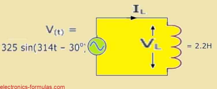
In this circuit, the supply voltage is given as V(t) = 325 sin(314t – 30°), and the inductance (L) is 2.2H.
Let's figure out the root mean square (rms) current flowing through the coil and create a phasor diagram to visualize the results.
Understanding Voltage and Current in a Coil
Equivalent RMS Voltage
The RMS voltage across the coil matches the supply voltage. If the power supply's peak voltage is 325V, the equivalent RMS value is 230V, represented as VL = 230 ∠-30° (volts).
Inductive Reactance
The coil's inductive reactance (XL) is found using ωL, with ω as 314 and L as 2.2, resulting in XL = 690Ω.
Current Flow Calculation
To determine the current flowing through the coil, we can apply Ohm's law, as shown below:
IL = VL / jXL = 230∠-30° / 690∠90° = 0.33∠-120° Amp
Phasor Diagram with a 90° Current Lag
When the current lags the voltage by 90°, the resulting phasor diagram will look like this.

AC Inductance Example No. 2: Finding RMS Supply Voltage
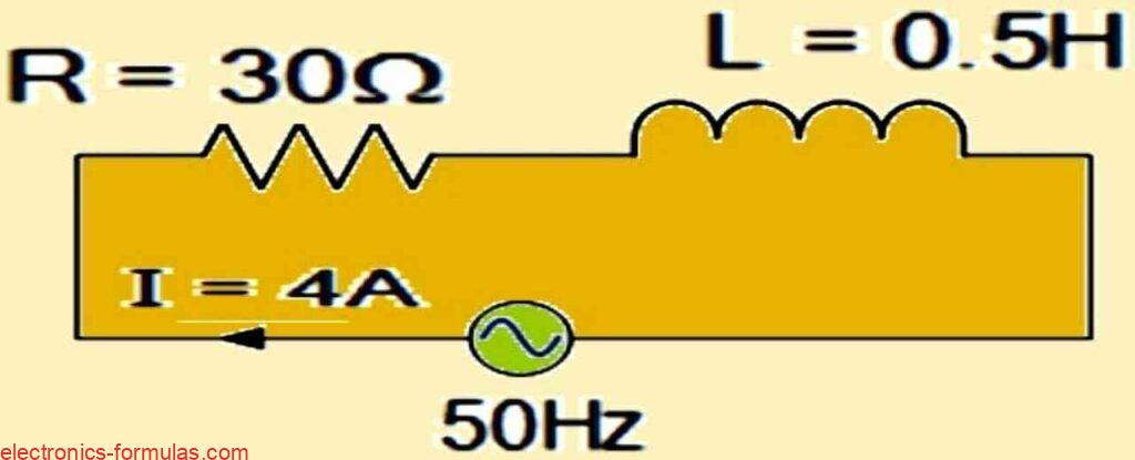
In this scenario, a coil with a resistance of 30Ω and an inductance of 0.5H has a current flow of 4 amps. To determine the rms value of the supply voltage at a frequency of 50Hz, let's explore the calculation.
We can calculate the impedance of the circuit using the following formula:
- XL = 2πƒL = 2π x 50 x 0.5 = 157Ω
- Z = √(R2 + X2L)
- Z = √(302 + 1572) = 159.8Ω
Determining Voltage Across Each Component
Next, the calculation involves determining the voltage drops across each component.
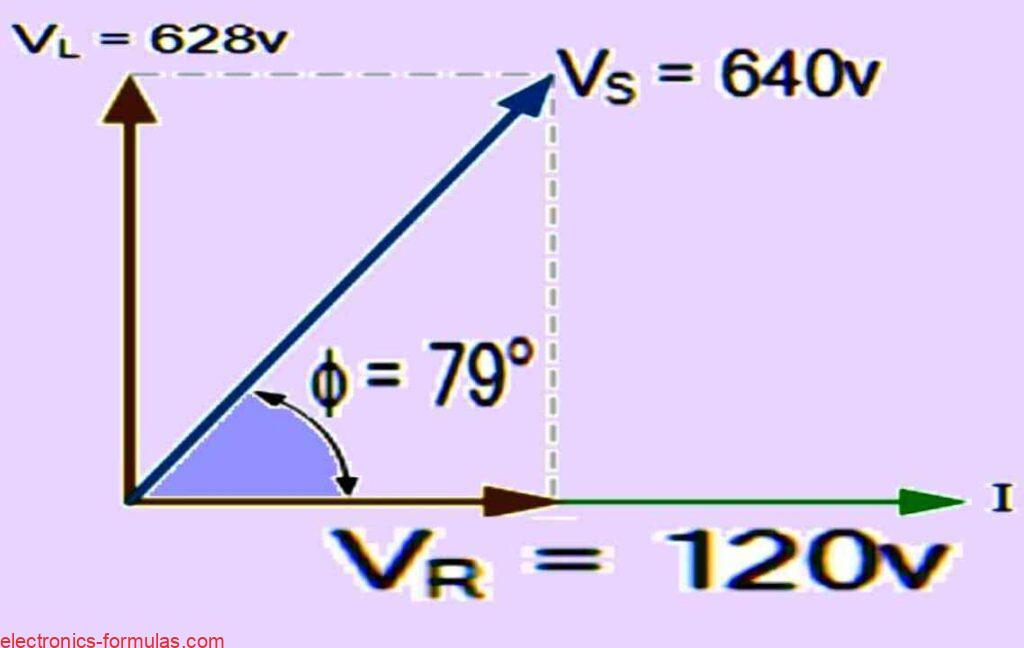
- VS = I.Z = 4 x 159.8 = 640V
- VR = I.R = 4 x 30 = 120V
- VL = I.XL = 4 x 157 = 628V
Calculating Phase Angle Between Current and Supply Voltage
The calculation involves determining the phase angle between the current and supply voltage.
Φ = tan-1Φ = XL / R = 157 / 30 = 79.2°
For a suitable phasor diagram, we can use the following diagram:
