So in our previous tutorial we already saw how a Thyristor or we can say Silicon Controlled Rectifier (SCR), is made and how that basic working happens. We saw how this device looks like and how it starts and stops conducting. That was only the construction and simple working part.
But now in this part, we will see something more useful. We will try to understand how we can use this Thyristor in real applications, like for controlling heavy loads. That can be things like electric lamps, heaters or maybe even motors etc. So this one is more practical.
How We Trigger the Thyristor
Now let us recall what we already said earlier. If we want to turn ON the thyristor then we must give one small current pulse at its Gate terminal. We should not give a continuous current there, only one quick pulse is enough. But that will work only when Anode is already positive compared to Cathode. So Anode must be at higher voltage than Cathode. Then only that regenerative latching can happen properly.
That triggering pulse does not need to be very long. Just a few microseconds is enough. But if we keep that Gate pulse for a little longer then that internal avalanche breakdown happens faster and thyristor turns ON more quickly. But at same time, we must not cross the maximum Gate current limit, otherwise the device can get damaged.
Once we give the pulse and thyristor starts conducting then that voltage between Anode and Cathode becomes fixed at around 1.0V. This drop stays more or less same for any current up to its rated level.
Thyristor Keeps Conducting Even Without Gate
Now one important thing we must always remember. After that thyristor starts conducting then it will continue to conduct current even if we remove that Gate signal. So Gate pulse is only needed for triggering, not for keeping it ON.
It will keep passing current until the Anode current drops below one small value which we call holding current or IH. When the Anode current becomes less than this IH value then only thyristor will switch OFF automatically.
Thyristor is Not Like a Transistor
So now we have to understand this thing very clearly. This thyristor is not like a BJT or a FET. Those transistor types can be used for amplification and smooth switching. But thyristor is totally different.
Thyristors are made specially only for high power switching work. That means they are not amplifiers. They can only act like a switch – either fully OFF or fully ON – nothing in between.
In DC and Inductive AC Loads, We Need Extra Turn OFF Circuit
Now one last thing, if we are using thyristor in DC circuits or in AC circuits with high inductance then it will not turn OFF by itself. Because in those cases the current may not go below the holding current automatically.
So in such DC or inductive conditions, we must use a special circuit or switch to make the current drop or to force the thyristor to turn OFF. Otherwise it will just stay ON forever once triggered.
How Thyristor Works in DC Circuit
So now let us try to understand how this thyristor behaves when we connect it with a DC power supply. That means, instead of AC we are using plain direct current. In this condition, we can use the thyristor like a DC switch. It can control big DC loads by switching them ON or OFF.
Now when we use thyristor like a switch in DC then it starts behaving like an electronic latch. That means, once we give one triggering pulse at the Gate and the thyristor turns ON then it will stay in that ON condition by itself. It will not go OFF automatically like in AC. It will keep conducting that big DC current until we manually force it to reset or switch OFF.
So this is why we call it a latching action in DC because once ON, it remains ON permanently unless we drop the current forcefully below the holding level.
Now let us look at the actual DC thyristor circuit diagram below and try to see how all parts are connected and how the load is controlled.
Simple DC Thyristor ON/OFF Switching Circuit
So now we are looking at this basic DC thyristor switching setup where we are using the thyristor just like a plain ON/OFF switch. In this example we are using a lamp as the load but we can use same idea to control any DC device like motor, heater, or any other heavy DC load also.
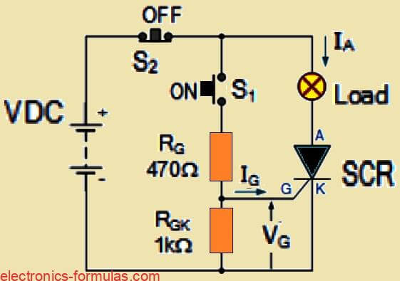
In this diagram we have one thyristor (SCR) connected in series with the lamp and the DC supply. The thyristor is already forward biased because the Anode is positive with respect to Cathode. But it will not conduct until we give a Gate trigger.
How the Gate is Triggered
Now if we want to switch ON the thyristor then we must press the normally open ON push button, which is marked as S1. When we press this S1 button, it connects the Gate terminal to the positive side of the DC supply through the Gate resistor RG.
So when we press S1, a small current flows through RG and enters the Gate. That current is called IG, the Gate current. This triggers the thyristor and makes it conduct.
But we must also be careful about the value of this Gate resistor RG. If we choose a very high resistance value then the Gate current might become too small. In that case the thyristor may not even trigger ON. So RG should be selected properly depending on the supply voltage.
Self Latching of the Thyristor
Now once the thyristor turns ON after pressing S1, it becomes latched. That means, even after we release the button still it will stay ON by itself. It will continue to conduct full load current through the lamp and back to the battery.
This latching action will only work as long as the load current is higher than the thyristor’s latching current. If that condition is fulfilled then the SCR stays ON always. After this, pressing S1 again will not do anything because the Gate loses its control after latching.
Why Thyristor is Useful in DC Circuits
One of the biggest advantages of using a thyristor in DC switching is that it has a very high current gain. This means we are using one small Gate current to control a much larger Anode current. So with a tiny input signal, we are switching a heavy load. That is why we say that the thyristor is a current operated device.
Use of RGK Resistor
Now we can see in the circuit that one more resistor is there between Gate and Cathode. That is called RGK and it is mostly 1kΩ. This resistor is used for reducing the sensitivity of the Gate. It also improves the dv/dt handling of the SCR and helps prevent any false triggering due to sudden voltage spikes or noise.
Turning OFF the Thyristor
After the SCR is latched and conducting, then we need to stop it somehow. We cannot use Gate for this. So we must reduce the Anode current below the thyristors holding current (IH). That is the only way to turn it OFF.
In our circuit, this job is done by the normally-closed OFF push button which is shown as S2. When we press S2, it opens the circuit and cuts the current flow to zero. This automatically shuts OFF the thyristor, and it goes back to its non-conducting state.
Now it will stay OFF until we press the ON switch (S1) again to restart it.
One Problem with the OFF Switch
But here one drawback comes. Since the OFF switch S2 is breaking the main load current, it must be strong enough to handle that full power. That means it must be a big mechanical switch. If the lamp or load takes a lot of current then the S2 switch must also be heavy-duty.
At this point, someone might think – “Why use thyristor at all? Let us just use one big mechanical switch to control the load directly.”
A Smarter Way to Improve the OFF Control
To solve this problem and avoid using a bulky mechanical switch for OFF control, we can do one small trick. We can connect the OFF switch in parallel with the thyristor, instead of putting it in series. That way we can use a smaller OFF switch and still manage to break the latching current by shorting or bypassing it briefly.
Another Way to Construct a DC Thyristor Circuit
So now in this alternative version of the circuit, we are still using the thyristor in same way like before. That means, it is getting the proper terminal voltage from the supply, and it is also receiving the Gate pulse signal for triggering, just like earlier.
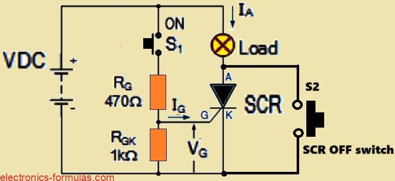
But now we have changed something in the OFF side of the setup. Earlier we were using one big, normally-closed switch in series with the load to break the main current. That switch had to handle full power. But now we have replaced that bulky switch with a smaller, normally-open push button and this one is connected in parallel across the thyristor’s Anode and Cathode terminals.
How the Parallel OFF Switch Works
So when we press this smaller switch which is again marked as S2, it short-circuits the thyristor from outside. That means it gives a temporary low-resistance path between Anode and Cathode directly.
Because of this action, the main current through the thyristor suddenly drops to zero or at least goes below its holding current value. And once the current falls below that IH level, the thyristor automatically stops conducting, and it turns OFF fully.
So this way we can reset or stop the thyristor using a small, low-current switch and we do not need that big OFF switch anymore.
Thyristor in AC Circuit – Behavior is Different
Now when we connect a thyristor in an alternating current (AC) circuit instead of DC then its behavior changes. It does not work like how it was doing in DC.
This happens because in AC, the polarity of the voltage keeps reversing continuously in every cycle. So during one half of the AC cycle, the thyristor will be forward biased and may conduct if triggered. But in the next half cycle, the polarity becomes reverse.
When that happens, then thyristor automatically becomes reverse biased and it turns OFF all by itself, even if the Gate pulse is still present.
So in AC circuits, a thyristor will always stop conducting once per cycle during the reverse half. That is why its working in AC is self-resetting on every cycle, unlike DC where we had to manually drop the current.
Now let us see the actual AC thyristor circuit diagram in the next part and try to understand how this self-commutation happens in each AC cycle.
Basic AC Thyristor Firing Circuit – How It Looks
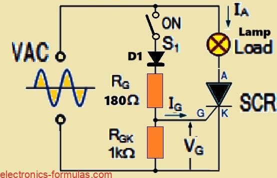
So now we are seeing one basic thyristor firing circuit which works with AC supply and it looks almost same like the earlier DC SCR circuit. The main layout is similar but here we do not have that extra “OFF” switch like before. That part is removed.
Instead now we have one diode D1 added in the Gate path. This diode is very important here because it blocks the reverse voltage from entering the Gate terminal. So it protects the thyristor Gate from getting reverse biased.
What Happens When Switch S1 is Open
Now let us see how this circuit works during one full AC cycle. So during the positive half-cycle of the AC waveform, the thyristor becomes forward biased, that means Anode is positive compared to Cathode.
But if switch S1 is still open, then no Gate current will reach the thyristor. So nothing will happen. The thyristor will stay in OFF state, because no trigger current is present at the Gate.
Then comes the negative half-cycle of the AC. In this part, the thyristor gets reverse biased, so naturally it cannot conduct. In this case even if we close switch S1, still nothing will happen. The device will stay completely OFF during the negative side of the sine wave.
What Happens When We Close Switch S1
Now suppose we close switch S1. That means now the Gate is connected to the positive supply through diode D1. So at the beginning of the next positive half-cycle, thyristor is again forward biased but still OFF because voltage is small.
But just after few degrees of the waveform, the voltage rises enough to send trigger current into the Gate through S1. This causes the thyristor to turn fully ON and then the lamp also turns ON immediately.
Once it turns ON then thyristor becomes latched and now Gate has no more effect. Gate is practically shorted to Cathode from inside, so it does nothing. The thyristor continues conducting during the entire positive half-cycle.
Automatic Turn OFF at End of Positive Half-Cycle
This conduction continues till the AC waveform reaches zero volts which happens at 180 degrees. At that moment, the Anode current becomes less than holding current and thyristor automatically switches OFF.
Then in the next negative half-cycle again the thyristor stays OFF due to reverse polarity. So nothing happens in that time. After that again in the next positive half-cycle, same process repeats, that is, thyristor waits till Gate gets enough voltage then it fires, then conducts, then turns OFF at 180 degrees.
Lamp Gets Only Half Power in This Setup
So now if switch S1 stays closed all the time then the thyristor will keep turning ON in each positive half-cycle only and stay OFF in negative half-cycle. That means, the lamp will receive only 50% power or half of the total AC power.
Here thyristor is acting just like a diode, allowing current to flow only in one direction, the forward part. So this becomes like a half-wave controller circuit for AC.
What If We Trigger Thyristor at a Later Angle?
Now suppose we want to control the power more accurately. Then we can try to give the Gate pulse not at beginning but at some delay, like at 90 degrees which is the peak point of the sine wave.
If we do that then thyristor will start conducting only from 90 degrees to 180 degrees. So instead of full half-cycle, it will conduct in only one half of that half-cycle.
This means the lamp will get only one-fourth (25%) of total power from AC supply.
Controlling Power from 0% to 50%
So now we know that if we keep delaying the Gate pulse more and more from 0 degrees to 180 degrees, then we can control how much power the load receives. By carefully adjusting the timing of the Gate pulse, we can give any power between 0% to 50% to the lamp.
We cannot go above 50% here because thyristor never conducts during negative half-cycle. It is always OFF there due to reverse bias.
So in this firing method, maximum possible power delivery is only 50%. Let us now see the exact circuit diagram for this below and try to understand more deeply how it works.
What is Phase Control in AC Thyristor Circuits
So now we are talking about one very popular and most commonly used method of controlling AC power using a thyristor. That method is called phase control. This technique is used in many power control applications where we want to adjust how much AC power is going to the load.
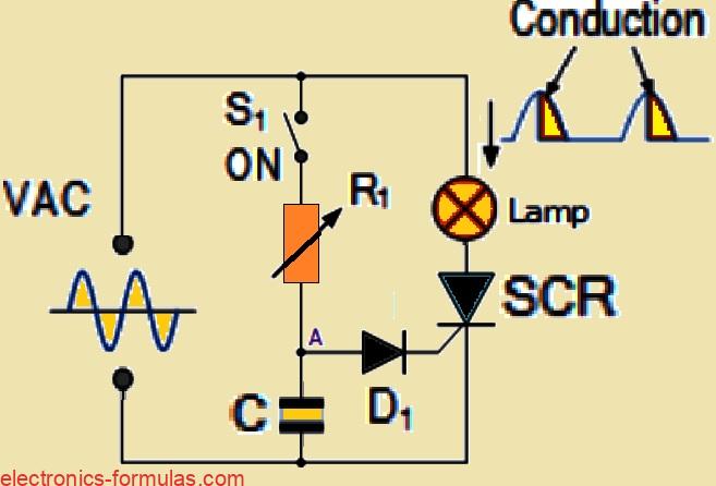
We can build a basic AC phase-control circuit using very simple parts and one example is shown in the diagram above. In this setup the Gate voltage for the thyristor is taken from one RC charging circuit, and this RC circuit is connected through one trigger diode which is marked as D1.
How the Circuit Works in Each Positive Half-Cycle
So now let us see how this works. During every positive half-cycle of the AC waveform, the thyristor becomes forward biased. At the same time, the capacitor C starts charging up slowly through resistor R1, and this charging follows the rising AC voltage.
Now the Gate of the thyristor does not get triggered immediately. It will turn ON only when the voltage at point A becomes high enough to make the trigger diode D1 conduct. So D1 decides the exact moment when the Gate pulse happens.
How the Capacitor Triggers the Thyristor
Once the voltage across the capacitor reaches the trigger point of diode D1 then this diode starts conducting. At that moment, the capacitor suddenly discharges and sends one pulse into the Gate terminal of the thyristor.
This Gate pulse is enough to fully turn ON the thyristor and it starts conducting load current for the rest of that positive half-cycle.
How We Control the Trigger Angle with R1
Now the interesting thing is, we can control the timing of this triggering by adjusting the RC time constant. This time constant is set using resistor R1 and capacitor C. But usually in this setup, only R1 is made variable (like a potentiometer), and C is kept fixed.
If we increase the resistance of R1, then the capacitor will take more time to charge up. That means the Gate pulse will come late so the thyristor will turn ON later in the cycle. This delays the conduction angle and reduces the power given to the load.
So now by simply rotating the knob of R1, we can change the conduction starting point anywhere between 0 degrees to 180 degrees of the sine wave.
Adjusting Power Delivered to the Load
This late or early triggering means we are changing the amount of time thyristor stays ON in each half-cycle. That directly changes the average power that is going to the load, like a lamp.
So more delay means less power and less delay means more power. But because this thyristor can conduct only in one direction, it can never give more than 50% power in total. That is because it stays OFF in every negative half-cycle of the AC waveform.
How to Get Full-Wave AC Control
Now suppose we want to go beyond that 50% limit and want to control full AC power then we have to use some extra tricks.
One method is that we use only one thyristor, but we place it inside a diode bridge rectifier. This rectifier converts the full AC into unidirectional DC pulses, so now the thyristor will see forward current in both half-cycles and we can control total power.
But the more popular method is to use two thyristors connected in inverse-parallel. That means both thyristors are facing opposite directions and control opposite halves of the AC cycle. So now we can control the full waveform.
Using a TRIAC – Better and Easier
But there is one more simple and practical solution. We can just use a TRIAC instead of two thyristors. A TRIAC is a special device that is like two thyristors in one body and it can be triggered in both directions.
That means TRIAC can conduct both positive and negative half-cycles, and it is perfectly suitable for AC power switching and full-wave phase control applications.
So TRIAC becomes the best option for fan dimmers, light dimmers, heater controllers, and many other AC-based applications.
References:
Leave a Reply