Passive components control or limit electrical signals, but can’t amplify them. Meaning, they can affect the signal in various ways, but not boost its power.
In an electrical circuit we connect various parts to create a closed loop where electricity can flow. Three key parts that are involved are resistors, capacitors, and inductors.
These are all considered “passive” because they don’t generate power on their own, but rather affect how electricity behaves in the circuit.
There are two main types of electrical current: direct current (DC), which flows steadily in one direction, and alternating current (AC), which constantly switches direction. Interestingly, even though these passive components can limit the flow of electricity, they act differently in AC circuits compared to DC circuits.
Passive components are like brakes on an electric current. They use up some energy but don’t add any themselves.
This means, they can’t boost a signal’s strength (gain is less than one).
The cool thing is that, you can connect these passive components in countless ways to create circuits with unique behaviors.
These behaviors depend, on how the electrical properties of each component interact with each other.
Working of Passive Components in AC Circuits
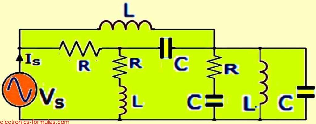
In the above diagram:
- R represents resistance (opposition to current flow)
- C represents capacitance (ability to store electrical energy)
- L represents inductance (opposition to changes in current)
Resistor = Consistent Opposition, No Matter the Current:
Resistors are special, because their resistance (opposition to current flow) stays the same, regardless of whether they’re in a direct current (DC) or alternating current (AC) circuit.
This is because, we idealize resistors as pure, meaning they have zero capacitance (think of it as storage for electrical energy) and infinite inductance (opposition to changes in current).
In other words they don’t store or fight against changes in current.
Another cool fact about resistors is that, in a circuit with only resistors, voltage and current are always in sync.
This perfect alignment makes it simple to calculate the power used at any moment, by just multiplying the voltage by the current.
Capacitors and Inductors: AC Resistance with a Twist
Unlike resistors, capacitors and inductors don’t have a simple fixed resistance in AC circuits. Instead they exhibit a special type of AC resistance called reactance (denoted by XL for inductors and XC for capacitors). Although both reactance and resistance oppose current flow, reactance is a trickier customer.
Here’s why: Unlike a resistor’s constant value, the reactance of a capacitor or inductor depends on two things:
- The frequency of the current: Higher frequencies mean different levels of reactance, for both capacitors and inductors.
- The component’s own properties: The specific capacitance or inductance value of the component itself also influences its reactance.
So unlike resistors, which present always the same opposition for current, capacitors and inductors introduce a variable known as reactance, which depends on frequency.
Understanding AC Circuit Components!
The list below investigates into some common passive components used in AC circuits, along with equations to calculate their properties or circuit current.
It’s important to note that, ideal capacitors and inductors have zero resistance, but real-world components always have some, even if tiny.
- Below we’ll explore equations for components.
- Remember, perfect components lack resistance, but real ones may have a bit.
Circuits with Only Resistors
In the world of electrical components, resistors are the reliable workhorses. They control the flow of current in a circuit like a dimmer switch for electricity.
This resistance is measured in ohms (Ω), and can be either fixed (like a regular resistor) or adjustable (like a potentiometer).
How it works: Resistors oppose the flow of current causing a voltage drop across them. This is why they are often used to control voltage levels in circuits.
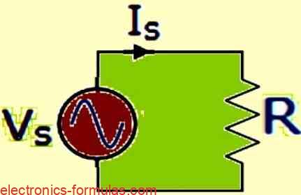
- Z = VR / IR = R
- Z = ∠0° = R + j0
- Is = Vs / R
Circuits with Only Capacitors
Think of a capacitor as a tiny battery for electricity. It can store electrical energy in the form of a charge. The more it can store, the bigger its capacitance, measured in Farads (F).
Here’s the interesting part about capacitors:
- In DC circuits (direct current, steady flow) capacitors act like an open circuit (almost no current flow) – like a gap in a wire. We call this infinite impedance (represented by XC).
- In very high-frequency AC circuits (alternating current, constantly changing direction) capacitors act like a closed circuit (easy current flow) – like a completed wire. In this situation their impedance becomes zero.
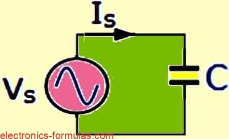
- XC = VC / IC = 1 /2πfC
- Z = ∠-90° = 0 – jXC
- IS = VS / XC
Circuits with Only Inductors
Imagine a coiled wire. When electricity flows through it, the coil creates a magnetic field, like a tiny electromagnet. This cool property is called inductance, measured in Henries (H).
Here’s the intriguing aspect of inductors:
- In DC circuits (direct current, steady flow), they act like a closed circuit (easy current flow) – like a completed wire. This means, their impedance is zero.
- In high-frequency AC circuits (alternating current, constantly changing direction), inductors resist changes in current flow, acting almost like an open circuit (very little current flow) – like a gap in a wire. We call this infinite impedance (represented by XL).
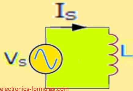
XL = VL / IL = 2πfL
Z = ∠+90° = 0 + jXL
IS = VS / XL
In AC circuits, we can connect passive components together in series. This indicates that, they are connected sequentially, one following another. These series combinations create different types of circuits, like:
- RC circuits: These involve a resistor (R) and a capacitor (C) working together.
- RL circuits: These combine a resistor (R) and an inductor (L).
- LC circuits: These feature a capacitor (C) and an inductor (L) in a series connection.
Series RC Circuit
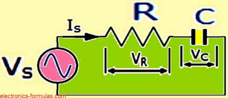
- Z = √(R2 + X2C)
- Z = ∠-Φ = R – jXC
- Φ(-90 🡢0) = tan-1(-XC/R)
- IS = VS / Z = VS / √(R2 + X2C)
- VS = √(V2R + V2C)
Series RL Circuit
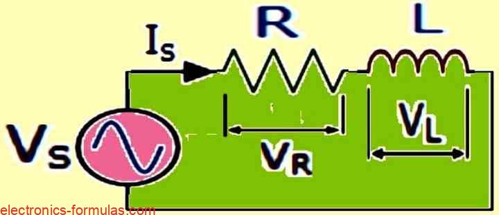
- Z = √(R2 + X2L)
- Z = ∠+Φ = R + jXL
- Φ(0 🡢90) = tan-1(XL/R)
- IS = VS / Z = VS / √(R2 + X2L)
- VS = √(V2R + V2L)
Series LC Circuit
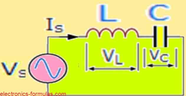
- Z = √(X2L + X2C)
- ∴ Z = XL – XC or XC – XL
- Z = ∠Φ + j = 0 + (jXL – jXC)
- fR = 1 / 2π√LC
- at fR , XL = XC and VL = VC
- IS = IL = IC
Passive Components in Parallel
We’ve seen how components connect in series, but there’s another way! In AC circuits, passive components can also be wired in parallel. Imagine each component having its own “lane” for current to flow through, side-by-side.
Just like series connections, these parallel combinations create various circuits:
- RC circuits: Again, this combines a resistor (R) and a capacitor (C), but in a parallel arrangement.
- RL circuits: Similar to the series version, this features a resistor (R) and an inductor (L) working in parallel.
- LC circuits: This parallel connection pairs a capacitor (C) with an inductor (L).
Parallel RC Circuit
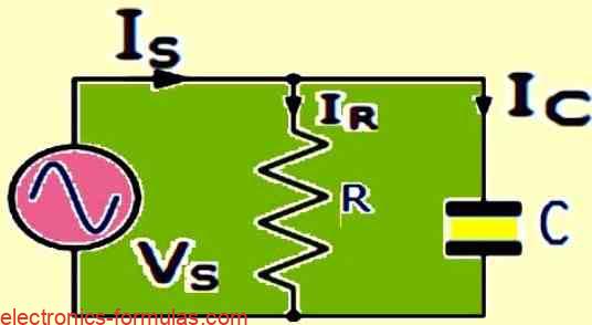
- IR = VS / R, IC = VS / XC
- IS = √(I2R + I2C)
- Φ = tan-1(IC/IR)
- Y = 1/Z = √(G2 + B2C)
- VS = VR = VC
Parallel RL Circuit
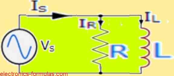
- IR = VS / R, IL = VS / XL
- IS = √(I2R + I2L)
- Φ = tan-1(IL/IR)
- Y = 1/Z = √(G2 + B2L)
- VS = VR = VL
Parallel LC Circuit
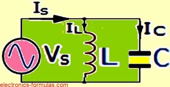
- BL = 1 / XL, BC = 1 / XC
- Y = 1 / Z = (-BL) + BC
- fR = 1 / 2π√LC
- at fR , XL = XC and IL = IC
- VS = VL = VC
Passive RLC Circuits
We’ve explored resistors, capacitors, and inductors individually and in pairs. But, in AC circuits, you can bring all three together to form even more complex circuits:
- Series RLC circuits: Imagine a resistor (R), a capacitor (C), and an inductor (L) connected in a chain, one after the other. This creates a special type of circuit with unique properties.
- Parallel RLC circuits: Here, the resistor (R), capacitor (C), and inductor (L) each have their own “lane” for current to flow, existing side-by-side. This parallel connection results in another exciting circuit type.
Series RLC Circuit
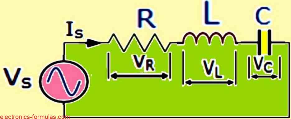
- Z = √[(R2 + (XL – XC)2]
- Z = ∠Φ = R + jX
- VS = √[V2R + (VL – VC)2]
- IS = VS / Z = VS / √[(R2 + (XL – XC)2]
- Φ = tan-1[(XL – XC) / R]
- IS = IR = IL = IC
Parallel RLC Circuit
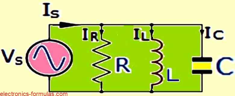
- G = 1 / R, BL = 1 / XL, BC = 1 / XC
- Y = 1 / Z = √[G2 + (BL – BC)2]
- IS = √[I2R + (IL – IC)2]
- fR = 1 / 2π√LC
- VS = VR = VL = VC
AC vs. DC: The Frequency Factor
In a circuit with only resistors (purely resistive), the current and voltage are always in sync, like two best friends walking in step.
But things get interesting with capacitors and inductors:
- Capacitors (purely capacitive circuits): Here, the current gets a head start! It leads the voltage by 90 degrees, like a runner starting slightly ahead in a race.
- Inductors (purely inductive circuits): In contrast, inductors make the current lag behind the voltage by 90 degrees. Imagine a slow walker lagging behind a faster friend.
This difference in timing is caused by frequency, which is a key concept in understanding AC circuits.
The Impedance
In DC circuits, resistance (R) is the only hurdle for current flow. But in AC circuits, things get more complex. Here’s why:
- Reactance: Capacitors (XC) and inductors (XL) introduce a new kind of opposition called reactance. It’s like a frequency-dependent resistance that affects how easily current flows.
- Impedance (Z): This combines the effects of resistance and reactance. Think of it as the total opposition to current flow in an AC circuit.
Phasor Power: Adding Things Up in AC Circuits
Regular addition works for DC circuits, but, AC circuits require a special technique called phasor addition. Here’s the gist:
- Series circuits: The voltages (not currents!) across each component (resistors, capacitors, inductors) are added using phasors. The sum must equal the total supply voltage (VS).
- Parallel circuits: In contrast, currents flowing through each branch (path) and each component are added using phasors. The sum must equal the total supply current (IS).
Phasors are like arrows that show both the magnitude and direction (timing) of voltage or current. This special addition helps us understand how components interact in AC circuits.
The Sweet Spot: Resonance in RLC Circuits
There is a special frequency in RLC circuits (both series and parallel) in which something magical happens: resonance.
At resonance frequency, the opposition from the capacitor (XC) exactly cancels out the opposition from the inductor (XL). Imagine a tug-of-war where both sides are perfectly balanced!
Here’s what resonance brings:
- In-phase current and voltage: When resonance occurs, the current perfectly aligns with the voltage, just like two synchronized dancers.
- Series vs Parallel Resonance:
- Series Resonance (Acceptor Circuit): In series circuits, this sweet spot allows the circuit to “accept” a specific frequency, letting more current flow through at that frequency.
- Parallel Resonance (Rejecter Circuit): In parallel circuits, resonance acts like a filter which “rejects” a specific frequency and forcing most of the current to take alternative paths.
Understanding resonance is crucial for designing circuits which can either boost, or filter out specific frequencies.
References:
Leave a Reply