
Here we will explore how circuits that contain resistors (R), inductors (L), and capacitors (C) respond to different frequencies. These circuits, called resonant circuits, behave differently depending on the frequency of the signal running through them. In this tutorial, we’ll focus on a specific type called a series resonant circuit. We’ll also learn how to […]
Calculating Parallel RLC Circuit

In contrast to the series circuit we examined in the previous tutorial, the Parallel RLC Circuit has the opposite characteristics. However, some of the concepts and equations we learned before are still relevant. To simplify the mathematical analysis of parallel RLC circuits, this tutorial assumes that the components are pure, meaning that they have no […]
Calculating Series RLC Circuits

In our earlier tutorials we have learned that Resistance, Inductance, and Capacitance, the three basic passive components, react differently to a sinusoidal alternating voltage in terms of phase. However, a series RLC circuit is formed by connecting passive elements, such as resistors, inductors, and capacitors, in series with a voltage supply. Voltage Waveforms in Pure […]
Calculating Capacitance and Capacitive Reactance
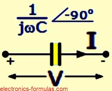
A capacitor is a device that can store electric charge on its conductive plates. The amount of charge (Q) that a capacitor can store depends on the voltage difference between its plates. When a capacitor is connected to an alternating current (AC) circuit, its capacitance affects how well it can store and release charge as […]
Calculating Resistance and Impedance

The term “resistance” refers to the opposition to current flow in a DC circuit, whereas the term “impedance” refers to the opposition to current flow in an AC circuit, measured in Ohms. Impedance is a combination of AC resistance and reactance, which effectively reduces the current flow. Phasor Representation in AC Circuits To represent complex […]
Calculating Inductance and Inductive Reactance

An inductive coil generates a self-induced electromotive force (emf) opposing the initial emf in response to an AC supply. This phenomenon, termed inductive reactance, imposes limitations on the flow of time-varying current in the circuit. Inductors and Energy Storage Inductors, also known as chokes, are coils wound around air or ferromagnetic material to enhance their […]