The term “resistance” refers to the opposition to current flow in a DC circuit, whereas the term “impedance” refers to the opposition to current flow in an AC circuit, measured in Ohms.
Impedance is a combination of AC resistance and reactance, which effectively reduces the current flow.
Phasor Representation in AC Circuits
To represent complex quantities in AC circuits with sinusoidal waves, we use complex numbers and phasors for voltage and current.
By converting waveforms to the phasor-domain, we can draw diagrams to analyze how voltage and current relate to each other.
AC Resistance in Basic Circuits
To apply phasor representation to basic elements in a single-phase AC supply circuit, such as resistors, we can use a mathematical description.
For resistors, Ohm’s Law states that the voltage is linearly proportional to the current.
Resistance in AC Circuits with a Sine Wave Voltage
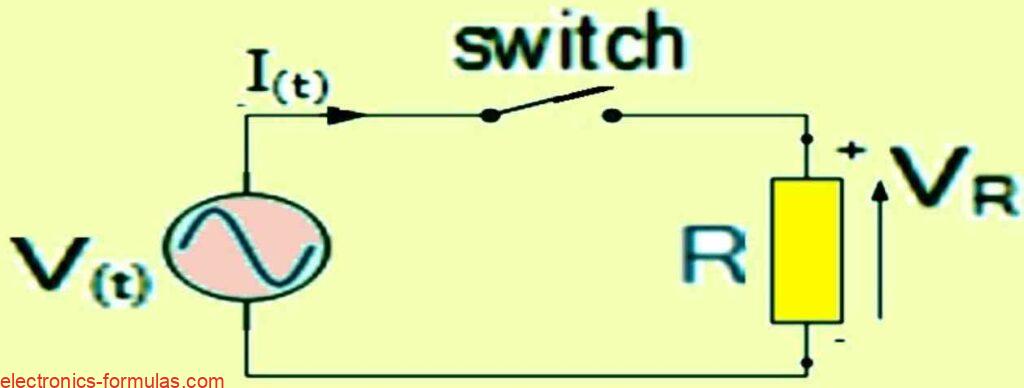
The resistor, R, receives an AC voltage, V, when the switch is turned on. The voltage induces a current that has the same sinusoidal pattern as the voltage.
The current and voltage are in phase, meaning they have the same peak or zero values at the same time. This is because the load is a resistor, which does not alter the phase of the current or voltage.

A resistor has an AC current that changes with a sine wave over time. The equation I(t) = Im x sin(ωt + θ) shows this current.
Im is the highest current value and θ is how much the wave is shifted. Also, Ohm’s Law says that the peak voltage across R is the same as the current, i, times R.
V(t) = R x It = R x Imsin(ωt + θ)
The current value at any given moment, i, will be:
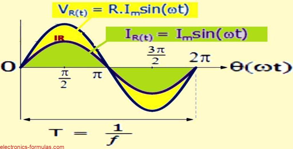
iR(t) = IR(max) x sinωt
In a purely resistive circuit, the resistor’s alternating current changes according to the applied voltage, following the same sinusoidal pattern.
The voltage and current have the same supply frequency, so their phasors are also the same. This means that the current is “in-phase” with the voltage, ( θ = 0 ).
A simpler way to say this is that the current and the voltage are in sync when using an AC resistance. They both reach their highest, lowest and zero values at the same time. Please see the following diagram:

We can also use a phasor diagram to show that the voltage and current are in-phase with each other when there is only resistance in the circuit.
This means that there is no imaginary or “j” part of the resistance in the complex domain. So, the phase difference ( θ = 0 ) between the voltage and current is zero, and they have the same reference axis on the phasor diagram.
A phasor-domain representation of a sinusoidal time-domain signal can be obtained by applying the following transformation.

A phasor differs from a vector in that it represents the RMS values of the voltage and current quantities, while a vector represents the peak or maximum values.
Therefore, if we divide the peak value of the time-domain expressions above by √2, we get the following voltage-current phasor relationship.
Formula showing relationship of RMS
- I = (Im / √2) (∠θA)
- V = (R x Im / √2) (∠θV)
- ∴ R = V / I = (R x Im / √2) (∠θ) / (R x Im) / √2 (∠θ)
Formula showing relationship of phase.
- V = R x I(RMS) ∠θ
- I = I(RMS) ∠θ
- V∠θv = I∠θi
- θv = θi
- both are in phase.
This means that a pure resistance in an AC circuit has the same effect on its voltage and current phasors as it would have on the voltage and current of a DC circuit.
In a DC circuit, this effect is known as Resistance, according to Ohm’s Law. But in a sinusoidal AC circuit, this effect is called Impedance. In other words, “Impedance” is the term for electrical resistance in an AC circuit.
A pure resistance always has a linear voltage-current (V-I) relationship in both AC and DC circuits.
When we use resistors in AC circuits, we usually call their resistance Impedance, with the symbol Z. So, for a resistor, we can say that DC resistance = AC impedance, or R = Z.
The letter, ( Z ), represents the impedance vector for an AC resistance value that has the same units of Ohm’s ( Ω ) as DC. Impedance, also known as AC resistance, can be defined as:
Z = V / I (ohms)
If you have a circuit with only resistors, the impedance is just the total resistance. Impedance is a complex number that changes with the frequency, ω, of the circuit when you have capacitors or inductors.
But for resistors, there is no change in impedance with frequency, and the imaginary part of the complex number is always zero.
So, the formula for impedance in a resistor-only circuit is just a real number:
Z = R + j0 = R (ohms)
We can write the instantaneous alternating voltage applied to the resistor as follows: v = Vmsin(ωt)
Similarly, we can write the instantaneous alternating current flowing through the resistor as follows: i = Imsin(ωt)
In a purely resistive AC circuit, the voltage and current are in phase, so the phase angle is zero. The power factor is the cosine of the phase angle, so it is also zero.
Therefore: cos 0o = 1.0. This means that the resistor consumes power instantaneously according to the formula:
- P = v x i = Vmsin(ωt) x Imsin(ωt) = VmImsin2(ωt)
- ∴P = (VmIm / 2) (1 – cos2ωt)
Because v and i have the same phase, the cos2ωt term becomes zero. Therefore, the power that the resistor uses in one complete cycle is:
P = (VmIm / 2) (1 – cos2ωt) = (VmIm / 2) (1 – 0)
∴Pmax = VmIm / 2 watts
or PRMS = (Vm / √2) x (Im / √2) = VRMS x IRMS watts
The average power in a circuit that has resistance or reactance depends on the phase angle.
In a circuit that has only resistance, the phase angle is θ = 0, so the power factor is one. Therefore, we can use Ohm’s Law to define the average power consumed by an AC resistance in a simple way as:
P = V x I = I2R = V2R
These Ohm’s Law equations are identical to the ones for DC circuits.
Therefore, the effective power that an AC resistance consumes in a full cycle equals the power that the same resistor consumes in a DC circuit.
This is because, in a purely resistive circuit, v and i are in-phase, so the power consumption is never zero.
Some AC circuits, such as heaters and lights, have only a pure ohmic resistance and negligible inductance or capacitance. They do not have any impedance.
To analyze AC circuits, we can apply Ohm’s Law, Kirchoff’s Law, and simple circuit rules to calculate and find the voltage, current, impedance, and power, just like in DC circuit analysis.
We should use RMS values only when using these rules.
Solving an AC Resistance Problem
An electric heating element has a resistance of 50 ohms when connected to an alternating current source.
It is connected to a single-phase AC power supply with a root mean square voltage of 220 V. Find the current that the power supply provides and the power that the heating element uses.
Draw a phasor diagram that shows how the current and voltage are related in phase.
Current can be calculated as:
I = V / R = 220 / 50 = 4.4 Amps
A formula to find the active power that the AC resistance uses is:
P = I2R = 4.4 x 4.4 x 50 = 968 watts
A resistive component has no phase difference, so θ = 0. The phasor diagram that shows this is:

Another example for Solving AC Resistance
A pure resistor of 50 Ohms is connected to an AC voltage source that has the following expression: V(t) = 100 x cos(ωt + 30°).
Find the impedance of the circuit and the maximum current that flows through it. Draw a phasor diagram to show the relationship between the voltage and the current.
VR(t) = 100 x cos(ωt + 30o) → VR = 100∠30° V
Using Ohm’s law we get:
IR = VR / R = 100∠30° / 50Ω = 2∠30° A
The phasor diagram that matches this situation is:

Conclusion
When you have an AC resistance that is purely ohmic, it means that the current and the voltage are in sync. They rise and fall together, without any delay or phase difference.
The current is always equal to the voltage times a constant factor, which is the impedance (Z) of the resistance.
Impedance is like AC resistance, but it can also include other effects like capacitance or inductance.
In a pure ohmic resistance, there are no other effects, so the impedance is just a real number that is the same as the resistance value (R). It has no imaginary part (j0), which would indicate a phase difference.
So you can use Ohm’s Law to find the voltage or current in an AC circuit with a pure ohmic resistance, just like you would in a DC circuit.
Leave a Reply