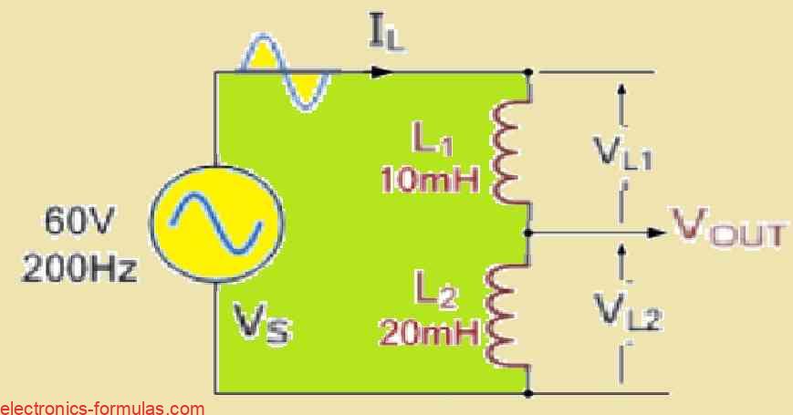
In many electrical circuits, inductive voltage dividers serve an important function in dividing an alternating current voltage source into smaller, more controllable voltages. The inductors in these circuits function by continuously resisting fluctuations in current. Inductors’ ability to effectively split voltage comes from this feature.
We can build an inductive voltage divider in different ways. We can make one by dividing a single coil into parts or by connecting numerous separate coils together. The autotransformer is a classic inductive voltage divider.
This adjustable transformer has several connections along its secondary winding, allowing it to provide a variety of output voltage levels.
Now, things get interesting when inductors are used in conjunction with voltage dividers. Inductors function as a dead short at extremely low frequencies, essentially DC. Inductors reject variations in current, and with constant DC, there is no change to resist!
As a result their reactance drops to nearly zero, enabling DC current to flow freely. This is why unlike capacitive dividers that operate on direct current, inductive voltage dividers require a sinusoidal AC source. The voltage division between inductors linked in series is calculated using their inductive reactance (XL).
This reactance, like capacitors, is proportional to the frequency of the alternating current source, the higher the frequency, the larger the reactance and its effect on voltage division.
Recall from our previous posts about AC circuits with inductors that we learned about inductive reactance, indicated by XL (and measured in ohms, like resistance). This reactance acts like a double-edged sword, meaning, it increases with both the frequency of the power source and the inductance itself. So, when you increase the frequency, your inductor’s reactance increases. Below is a useful formula for calculating inductive reactance:
The Inductive Reactance Formula
XL = 1 / 2πfL
In the above formula:
XL represents inductive reactance in ohms (Ω).
π (pi) is a fixed numerical constant of about 3.142, whereas f represents frequency in Hertz (Hz).
L stands for inductance in Henries (H).
The predictability of inductive voltage dividers is its most attractive feature. You can calculate the reactance of each inductor based on the voltage and frequency of your AC supply.
With this reactance in hand, you can apply the conventional voltage divider rule to calculate the voltage drop across each individual inductor.
Solving an Inductive Voltage Divider Problem

In the above figure, let’s examine the voltage drops that occur across each circuit inductor. Two inductors with 10 mH and 20 mH inductances are provided, and they are wired in series with a 60 V, 200 Hz AC source.
Calculating Inductive Reactance
The inductive reactance (XL) of an inductor is proportional to both its inductance (L) and the frequency (f) of the AC supply. We can calculate the reactance for each inductor using the following formula:
XL = 2 * π * f * L
where:
- XL is the inductive reactance in ohms (Ω)
- pi (π) is a mathematical constant approximately equal to 3.142
- f is the frequency of the AC supply in Hertz (Hz)
- L is the inductance of the inductor in Henries (H)
Inductance Values
L1 = 10 mH = 10 * 10-3 H
L2 = 20 mH = 20 * 10-3 H
Supply Voltage and Frequency
Vrms = 60 V (rms) f = 200 Hz
Calculating Reactance
XL1 = 2 * π * 200 Hz * 10 * 10-3 H = 12.56 Ω
XL2 = 2 * π * 200 Hz * 20 * 10-3 H = 25.13 Ω
Total Reactance
The total reactance (XLtotal) in the circuit is the sum of the reactances of the two inductors:
XLtotal = XL1 + XL2 = 12.56 Ω + 25.13 Ω = 37.69 Ω
Voltage Drop Across Each Inductor
To get the voltage drop (Vdrop) across each inductor, we may apply the voltage divider rule. In a series circuit, the voltage across each element is determined by multiplying the total voltage (Vrms) by the ratio of its reactance (XL) to the circuit’s total reactance (XLtotal), according to the voltage divider rule.
VdropL1 = Vrms * (XL1 / XLtotal) VdropL2 = Vrms * (XL2 / XLtotal)
Calculating Voltage Drops
VdropL1 = 60 V * (12.56 Ω / 37.69 Ω) = 20.0 V (rms) VdropL2 = 60 V * (25.13 Ω / 37.69 Ω) = 40.0 V (rms)
Conclusion
As long as we dont have any resistors in the series, the total voltage drop across both inductors will always equal the source voltage. This seems practical because all the energy from the source needs to be used up in the circuit.
Now, as we understand the voltage drop across each inductor is not equal. This actually depends on how much each inductor resists changes in current, which is captured by its reactance. As the reactance gets higher, the voltage drop across that particular inductor also gets higher.
In our example the 10mH inductor (L1) has a lower reactance (12.56Ω) compared to the 20mH inductor (L2) with a reactance of 25.14Ω. This gives rise to a smaller voltage drop of 20 volts across L1 compared to the 40 volts dropped across L2.
So we can conclude that, since these inductors are connected in series, the current flowing through them (denoted as IL) will be the same. In this case, the current is 1.6mA and will be identical for both L1 and L2.
References: Inductive voltage divider
Inductive voltage divider of simple design
Leave a Reply